


19
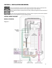
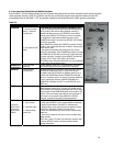
4.1.2. As a Generator subpanel: Models ATS1001D/R:
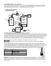
If using the Ovation™ Series ATS as a generator sub panel, mount the transfer switch as close to the load center as possible. The
OVATION™ ATS can be installed on either the left or right side of the load center. If flush-mounting is desired, the OVATION™ ATS
can be mounted in the adjacent stud space next to the existing load center.
1. Follow steps 1-2 as above.
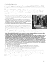
2. TURN OFF the main circuit breaker supplying power to
existing load center. Remove cover from load center.
3. Install appropriate sized conduit, fittings and wire
between transfer switch and load center to
accommodate all branch circuits that will be relocated to
the transfer switch and UTILITY MAIN feed (4 wire) from
load center to transfer switch.
4. Remove branch circuit wires from circuit breakers that
will be relocated to transfer switch. Remove two
adjacent single pole circuit breakers from which branch
circuit wires were removed. Install NEW 2-pole circuit
breaker (as noted in the Other Items Needed Section).
Circuit breaker must have the same rating as UTILITY
MAIN circuit breaker in transfer switch.
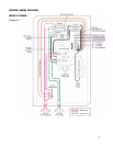
5. Connect UTILITY MAIN feed wire from new circuit
breaker in load center to UTILITY MAIN circuit breaker in transfer switch. The OVATION™ Series ATS have been UL Listed for
use with Copper or AL wire.
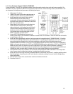
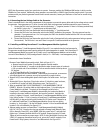
6. Install and connect appropriately sized wire from the generator to the terminals marked “GENERATOR MAIN”. If installing
the Current Sense Cable provided with the optional PowerPause™ Load Management Module Kit, each X and Y generator
source wire should pass through the hole of current transformer on the Current Sense Cable before connection to
GENERATOR MAIN circuit breaker. Ensure UTILITY and GENERATOR SENSE lead wires located in UTILITY and GENERATOR
MAIN circuit breaker lugs remain in the UTILITY and GENERATOR MAIN lugs when tightening the UTILITY and GENERATOR
MAIN source wire. When AL conductors are used, the application of a UL-Listed conductor termination compound is
recommended. Connect neutral and ground source wires from the utility and generator to the corresponding NEUTRAL and
GROUND bars. Refer to product label on transfer switch for correct terminal tightening torque requirements.
7. If the OVATION™ Series ATS is installed in new construction, affix paint/plaster shield to OVATION™ ATS to keep interior
clean. Remove when all wallboard and painting is completed and proceed to next step.
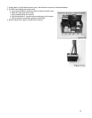
8. Install and wire the correct type and rating of compatible branch circuit breakers (see Section 2), complying with the product
label wiring diagram for each branch circuit. See the branch circuit breaker markings for correct wire size and tightening
torque requirements.
9. Ensure all wires are clear of the actuator/motor module and mechanical interlocks.
10. Proceed to Section 4.2.