


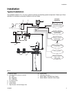
Installation
313855H 11
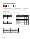
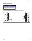
System Wiring
NOTE: On an AC controller (p/n 24B596), the J7 strip is line (input) voltage but the J6 strip is all 24VDC. On a DC
controller (p/n 24B59‘), the J6 and J7 terminals all carry the input voltage.
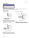
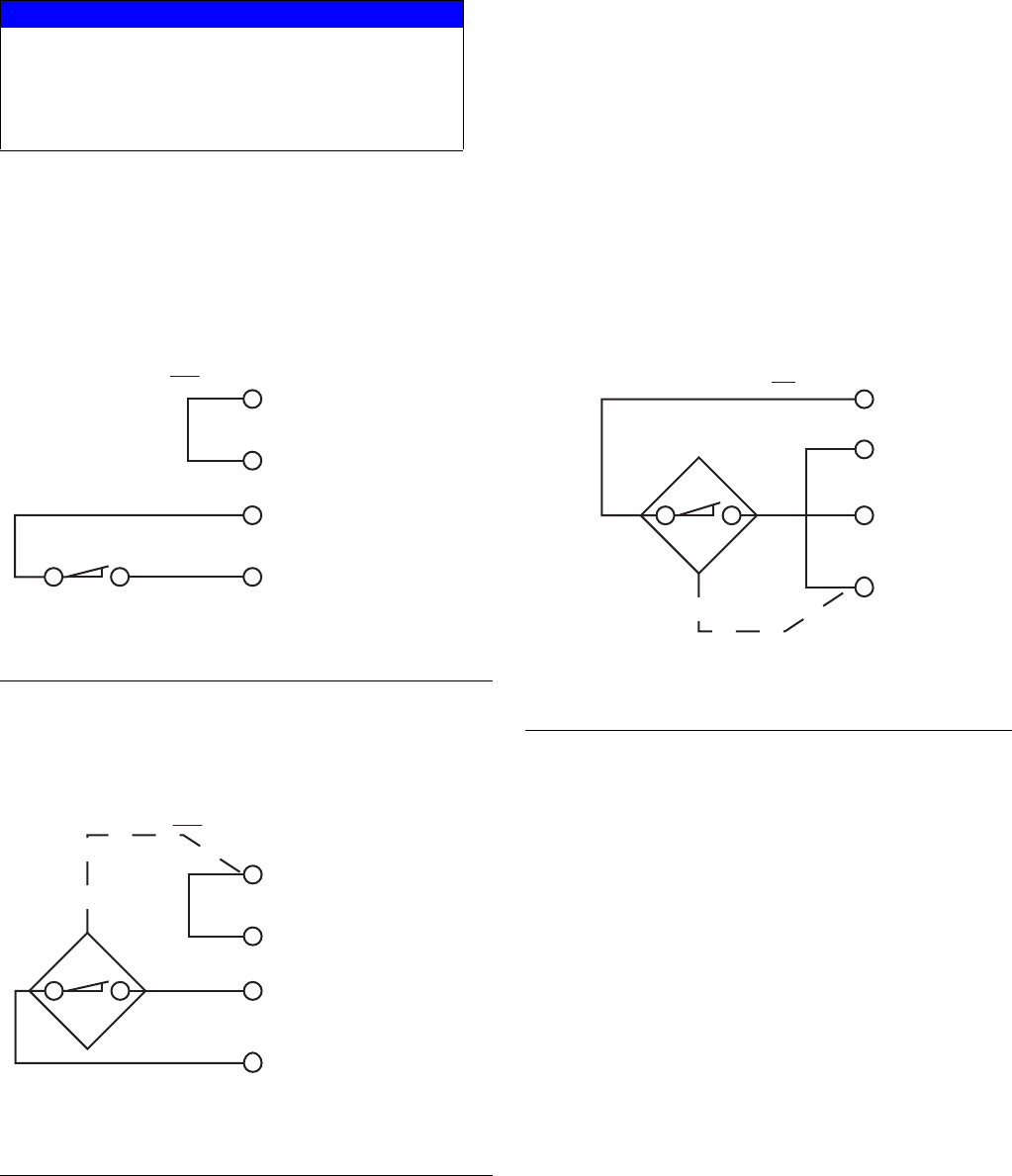
Input Sensor Wiring:
DRY CONTACT SWITCH
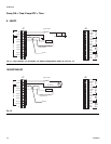
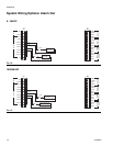
SOURCE SWITCH - 2 or 3 Wire Type
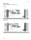
SINK SWITCH - 2 or 3 Wire Type
NOTICE
Do not connect any of the SW+ (13,9,5,1) and SW-
(16,12,8,4) pins together, either directly or via a
switch closure. Doing so will create a short circuit
condition which will disable and potentially damage
the controller.
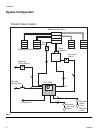
FIG. 8
F
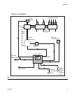
IG. 9
x = sensor input 1,2,3 or 4
1 (SW +)
2 (IN (x))
3 (SEN (x))
4 (SW -)
J6
1 (SW +)
4 (SW -)
J6
x = sensor input 1,2,3 or 4
2 (IN (x))
3 (SEN (x))
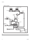
FIG. 10
1 (SW +)
4 (SW -)
x = sensor input 1,2,3 or 4
2 (IN (x))
3 (SEN (x))
J6