Setup
313855H 17
Setup
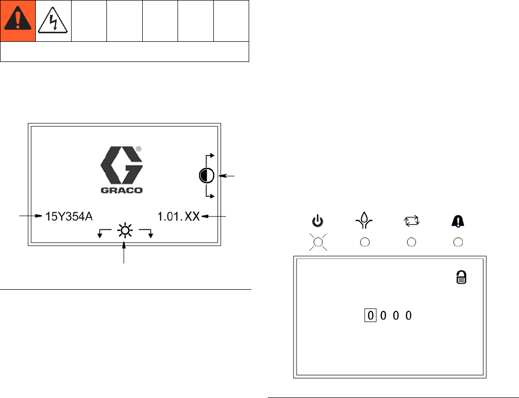
When you first turn on power to the Lubrication Control-
ler, the following identification screen displays.
A Display Contrast Adjustment: UP and DOWN
Arrows can be used to adjust the display contrast.
B Brightness Adjustment: LEFT and RIGHT Arrows
can be used to adjust the backlight brightness.
NOTE: Contrast and Brightness adjustments can be
made on any Run Screen at any time.
C Software (Part Number): 15Y354
D (Software) Version: 1.01.XX
NOTE: The example of the Software Version (D) shown
in F
IG. 20 displays “XX” as the last two numerals. On
your Controller’s screen, the “XX” will be replaced by the
current software version numbers.
System Setup - PIN Mode
Enabled
1. To access Setup Mode, hold down the ENTER key
for 3 seconds. The PIN ModeScreen shown in F
IG.
21 displays.
NOTE:
• The Pin Mode screen shown in F
IG. 21 only displays
when the PIN mode is enabled. For setting up sys-
tems when the PIN mode is not enabled, go to Sys-
tem Setup instructions on page 18.
• Before the PIN Mode screen shown in F
IG. 21 can
display, the PIN Mode must be enabled in an previ-
ous setup sequence. See PIN Setup, page 25.
2. The PIN Mode screen in F
IG. 21 displays.
NOTE: The PIN Code prompt spaces are initially blank.
3. Use the LEFT / RIGHT arrow to position the cursor
over the first blank PIN Code prompt field (F
IG. 21).
4. Use the UP/DOWN arrows to move up and down
through the numbers 0-9 until the first number in the
PIN code is displayed in the field.
5. Use the RIGHT arrow to move the cursor to the next
field.
6. Repeat steps 4 and 5 for each PIN Code prompt
field.
7. When finished, press ENTER.
See Electric Connection Warning, page 7.
F
IG. 20
FIG. 21


