


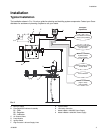

Installation
6 313855H
Installing the Lubrication Controller
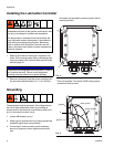
1. Select a flat surface to install the Lubrication Con-
troller. Drill mounting holes. Refer to Mounting Hole
Layout provided in the Technical Data section of this
manual, page 34.
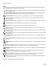
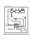
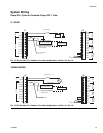
2. Remove Lubrication Controller cover and align junc-
tion box with predrilled holes (F
IG. 3, (a). Use four,
#6 screws (not provided) to secure junction box to
mounting surface.
* Parts not supplied. To maintain IP69K rating, proper
connectors must be used.
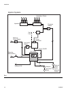
Grounding
The equipment must be grounded. Grounding reduces
the risk of static and electric shock by providing an
escape wire for the electrical current due to static build
up or in the event of a short circuit.
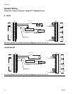
1. Loosen M6 screws from (b).
2. Attach up to 3 ground wires to (b) using appropriate
sized M6 ring terminal (not provided).
3. If more than 3 wires are used, attach necessary
amount of jumpers to other adjacent screw termi-
nals.
AUTOMATIC SYSTEM ACTIVATION HAZARD
Unexpected activation of the system could result in seri-
ous injury, including skin injection and amputation.
This device has an automatic timer that activates the
pump lubrication system when power is connected or
when exiting the programming function. Before you
install or remove the Lubrication Controller from the
system, disconnect and isolate all power supplies and
relieve all pressure.
NOTICE
Pre-drill and use designated mounting holes in Lubrica-
tion Controller box only. Failure to use designated
mounting holes can cause circuit board damage.
FIG. 3
a
a
a
a
*
FIG. 4
b
jumper
motor ground
sensor ground
ground