


Run Mode
32 313855H
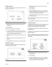
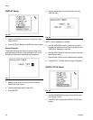
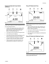
• The GLC 4400 pump output relay activates (J7-3)
and will stay off until the correct number of counts
(J6-15) occur (see Setup Menus, Pump Off, page
20).
• The Pump On LED (A) remains off during this time.
• The Pump Off icon (C) displays.
• The Cycle LED (B) and Machine Count icon (D) dis-
play and indicate the Machine Count Switch activa-
tion.
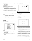
Pump Off Ended with Machine Counts; Max
Time Entered
If the Pump Off sequence has been programmed to be
ended by MACHINE COUNTS with a maximum time:
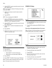
• The GLC 4400 pump output relay activates (J7-3)
and will stay off until the correct number of counts
(J6-15) occur (see Setup Menus, Pump Off, page
20).
• The Pump On LED (A) remains off during this time.
• The Pump Off icon (C) displays.
• The Cycle LED (B) and Machine Count icon (D) dis-
play and indicate the Machine Count Switch activa-
tion.
• The counts indicator bar (E) displays a visual repre-
sentation
of the machine counts received.
• If the set number of machine counts is not received
before time expires, an alarm occurs.
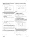
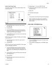
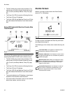
Alarms Screen
When a cycle alarm event occurs the Alarm Screen,
shown in F
IG. 62 displays.
To clear an alarm, hold down the Clear Key on the dis-
play Keypad (see page 3).
The following is a list of other alarm events that may dis-
play.
F
IG. 61
A
C
E
D
B
FIG. 62
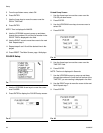
Low Level Alarm. Icon appears on display screen.
Indicates the lubrication fluid level is low.
Pressure mode error. Icon displays on alarm screen
to signal the allotted time ran out before the pressure
switch was tripped.
Machine count error. When icon displays on alarm
screen, indicates the set number of machine counts
was not received before time expired. This would
trigger an alarm event.
Cycle switch input error. Icon displays in center of
Alarm screen to indicate the allotted time ran out
before the programmed number of cycle switch
activations was received.