


Installation
313855H 5
Installation
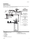
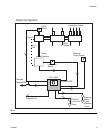
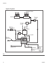
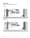
Typical Installation
The installation shown in FIG. 2 is only a guide for selecting and installing system components. Contact your Graco
distributor for assistance in planning a system to suit your needs.
A Main Air Supply
B Filter/Regulator/Lubricator Assembly
B1 - Filter
B2 - Regulator
B3 - Lubricator
C Air Solenoid Valve
D Pump Module
E Ignition Switch
F High-Pressure Lubricant Supply Lines
G Injector Banks
H Lubrication Controller
J Model 24B591 12/24VDC Power Supply
K Model 24B596 115/230VAC Power Supply
FIG. 2
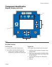
Controller
Capabilities
!
B1
B2
B3
C
E
H
G
F
D
Low Reservoir Level
switch (user provided)
Pressure or Cycle Switch
for system control
(user provided
Machine Counts for
System Control
(user provided)
Pressure Switch or Cycle
Switch Alarm
Low Level Alarm
Remote Alarm Device
(Light or Horn)
(user provided)
A
K
J