


Installation
313855H 15
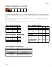
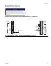
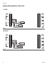
System Wiring Options
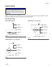
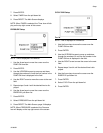
All Units: Low Level Switch / External Manual Run / O.K. Contact Out
NOTICE
Do not connect any of the SW+ (13,9,5,1) and SW-
(16,12,8,4) pins together, either directly or via a
switch closure. Doing so will create a short circuit
condition which will disable and potentially damage
the controller.
FIG. 17 Dry Contact, FIG. 8 shown. For other configuration, see FIG. 9 or FIG. 10.
16 (SW-)
15 (SEN4)
14 (IN4)
13 (SW+)
12 (SW-)
11 (SEN3)
10 (IN3)
9 (SW+)
8 (SW-)
7 (SEN2)
6 (IN2)
5 (SW+)
4 (SW-)
3 (SEN1)
2 (IN1)
1 (SW+)
1(IN)
2(COM)
3(OUT1)
4(COM)
5(OUT2)
6(COM)
7(OUT3)
8(COM)
9(OUT4)
10(OUT4)
11
OUTPUTS
-PWR+
J6J7
Manual
Low
Level
Press/
Cycle
Count
O.K. Contact
(Closed = O.K.)
Dry Contact Switch
Dry Contact Switch
*
*
NC