


8Ć27 Removal and ReplacementC3187Ć90000
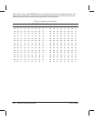
Table 8-1. EEROM Map
Address
Li
Definition
Location
00
Value=55 if EEROM has been initialized (Read by servo processor)
01 Value=AA if EEROM has been initialized (Read by servo processor)
02 Value=5A if EEROM has been initialized (Read by servo processor)
10 Byte 0 of the number of bench-run cycles completed
11 Byte 1 of the number of bench-run cycles completed
15 Number of stepper cycles per bench-run cycle
16 Byte 0 of the total number of bench-run cycles
17 Byte 1 of the total number of bench-run cycles
18 Number of waits per bench-run cycle
19 Number of bail cycles per print in bench run
1a Number of swaths per bench-run cycle
1b Media-sensor correction factor. (Calculated during media-sensor calibration)
33 (bit 6) Bit 1 (MSB) of bail-calibration (00 = not calibrated; 11 = calibrated;
status.. 01 and 10 = calibration in process)
33 (bit 7) Bit 0 (LSB) of bail-calibration status.
36 (bit 7) Need-cartridge-alignment flag. (1 = needs cartridge alignment)
37 (bit 0) Valid-cartridge-alignment flag. (1 = alignment performed OK)
39 PWM for carriage LED (calculated during cartridge alignment)
3d Byte 1 of media-axis alignment distance. (Positions engagement lever.)
3e Byte 0 of media-axis alignment distance.
Constants at address locations 3F through 4D are loaded
when the cartridge-alignment routine is performed.
3f Value used to correct position of carriage LED relative to media axis.
40 Value used to correct position of carriage LED relative to carriage axis.
41 Cartridge offset. (Used to correct distance between the two cartridges.)
42 Bi-directional offset in columns. (Used to compensate for differences between ink-drop
trajectory when carriage is moving from left to right and that when carriage is moving
from right to left.)
4b High-velocity factor, scaled by 64. (Used to adjust the bidirectional offset when the plot
quality is set to draft mode.)
4d Cartridges’ first nozzles (Not all of the nozzles are used; there may be an overlap
between the two cartridges to allow for alignment. Bits 0 and 1 indicate the first nozzle
used on the right cartridge. Bits 2 and 3 indicate the first nozzle used on the left
cartridge.)
4e Drive-roller correction factor. (Calculated during accuracy calibration.)