


5Ć25 Functional OverviewC3187Ć90000
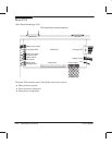
Serial Hardware The main processor controls the DTR (Data Terminal Ready) signal using
a bit in the parallel I/O control register. Whenever the power to the plotter is on, RTS
(Request To Send) is set active. No other modem signals are controlled or monitored.
Serial Input/Output Initialization The reset state of the DTR signal is undefined. During
initialization, the main processor first sets the DTR control bit to 1, which signals the host
that the interface cannot accept data. Later the processor sets the UART configuration
register and the baudĆrate select register using the configuration data from the EEROM.
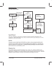
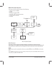
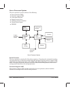
DRAM
Two MBytes of DRAM for system use and I/O data storage reside permanently on the Main
PCA. In addition, a 72Ćpin socket for the industryĆstandard DRAM SIMM is provided for
optional memory. The socket supports a DRAM SIMM of 2 MB, 4 MB, or 8 MB.
P owerĆOn Reset Signals
PowerĆon reset signals are used to initialize the processorĆsupport ASIC, shuffler ASIC and
servo processor. The processor support ASIC generates a reset signal to initialize the main
processor. A powerĆon reset signal disables the EEROM to prevent loss of data during power
transitions. The components that generate the reset signals guarantee valid signals once the
logic supply (+5V) exceeds 2.0 V.