


9Ć13 Product History and Service NotesC3187Ć90000
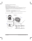
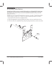
9. While softly pushing the camĆgear support all the way into the center of the gear, tighten
the two screws that attach the camĆgear support to the YĆtensioner bracket.
IMPORTANT: Ensure that the bailĆlift mechanism easily performs the engaging and
disengaging movement, by pushing the cam gear with your fingers.
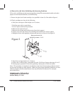
10. Tighten the right screw of the YĆtensioner bracket.
11.ĆReĆassemble the plotter and perform the calibrations in the following order:
a. Cap alignment (chapter 9)
b. Bail calibration (chapter 8)
c. Accuracy calibration (chapter 8)
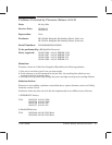
Administrative Information DRAFT SERVICE NOTE
Classification: Modification available
Reason: Serviceability & Reliability Enhancement
Action Category:
Location Category: OnĆSite
Availability: Product Support Life
Author/Entity: EV/F900
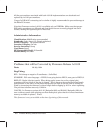
Change in Trailing Cable
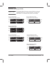
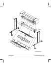
Early DesignJet 200 plotters were manufactured with the following trailing cable and
associated parts:
D Unshielded Trailing Cable, C3180Ć60007 (colored white on both sides)
D TrailingĆCable Rear Tray, C3180Ć00006
D Four Ferrites, 9170Ć1535
(two inside electronics enclosure, two on trailingĆcable rear tray)
D Four Ferrite Clamps, 9170Ć1533
Later DesignJet 200 plotters, and DesignJet 220 plotters, have a new trailing cable and
associated parts, improving electromagnetic compatibility and rendering unnecessary the
ferrites on the trailingĆcable rear tray:
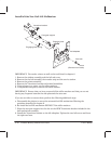
D Shielded Trailing Cable, C3180Ć60033 (colored white on one side, blue on the other side)
D TrailingĆCable Rear Tray, C3180Ć00040
D Two Ferrites, 9170Ć1535, inside the electronics enclosure
D Two Ferrite Clamps, 9170Ć1533
The shielded trailing cable is NOT compatible with old main PCAs (C3180Ć60101,
C3180Ć68101, C3180Ć69101).