Chapter 1 Before You Begin 21
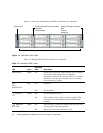
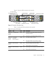
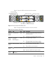
Figure 1-5 shows the LEDs at the back of the drive enclosure.
Figure 1-5 Drive Enclosure LEDs (Back View)
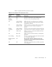
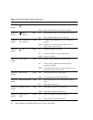
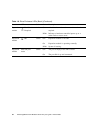
Table 1-8 describes the LEDs on the back of the drive enclosure.
Table 1-8 Drive Enclosure LEDs (Back)
Location LED Color State Description
Power and
cooling
module
AC Power Good Green Off AC power is off or input voltage is below the
minimum threshold.
On AC power is on and input voltage is normal.
Power and
cooling
module
DC Voltage/
Fan Fault/
Service Required
Amber Off DC output voltage is normal.
On DC output voltage is out of range or a fan is
operating below the minimum required RPM.
Expansion
module
SAS In port status Green Off The port is empty or the link is down.
On The port link is up and connected.
Expansion
module
Unit Locator White Off Normal operation.
Blink Physically identifies the expansion module.
Expansion
module
OK to
Remove
Blue Off Not implemented.
Service
0 0
Service
0 0
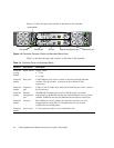
AC Power Good
Service Required
DC Voltage/Fan Fault/
SAS In port status SAS Out port status
Unit Locator
OK to Remove
Fault/Service Required
OK


