


32 HP StorageWorks 2012i Modular Smart Array user guide • March 2008
Connecting Controller and Drive Enclosures
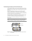
Use the supplied SAS cables to connect a controller enclosure to up to three drive
enclosures. Figure 2-4 and Figure 2-5 show the recommended fault-tolerant cabling
patterns. In an enclosure, the upper module is designated A and the lower module is
designated B.
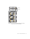
When connecting multiple drive enclosures, use reverse cabling to ensure the
highest level of fault tolerance. For example, Figure 2-5 shows controller A
connected to expansion module 1A, and the chain of connections continuing down.
Controller B is connected to the lower module (B) of the last drive enclosure in the
chain, with connections moving in the opposite direction.
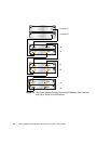
Fault-tolerant cabling is recommended because it enables the controllers to access
remaining drive enclosures if any one drive enclosure fails. However, the system
also supports non-fault-tolerant cabling using the supplied SAS cables.
Figure 2-6 shows non-fault-tolerant cabling between a controller and up to three
drive enclosures.
Note – For clarity, the schematic illustrations of the controllers shown in this
section show only relevant details such as expansion ports. For detailed illustrations
showing all components, see “Hardware Components and LEDs” on page 13.
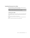
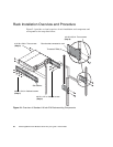
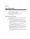
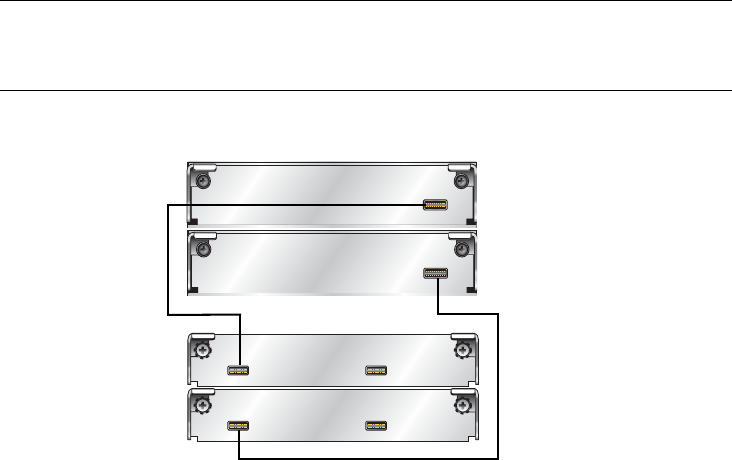
Figure 2-4 Cabling Connections Between One Controller Enclosure and One
Drive Enclosure
In Out
In Out
Controller B
Controller A
1A
1B