


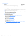
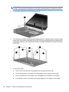

NOTE: When replacing the display assembly, only replace the four bottom screws in the display
brackets. The top screw on the bracket on each side is replaced when you install the top cover.
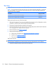
4. Lift the display assembly up and off the computer (2).
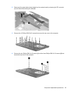
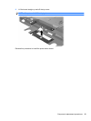
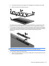
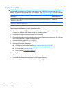
5. If it is necessary to replace the display bezel, display enclosure, or display hinges, remove the eight
rubber screw covers (1) and the eight Phillips PM2.5×6.0 screws (2) that secure the display bezel
to the display assembly. The rubber screw covers are available in the Rubber Kit, spare part number
535793-001.
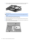
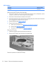
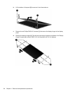
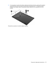
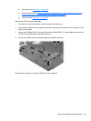
6. To remove the bezel:
a. Flex the top of the bezel until it disengages from the display enclosure (1).
b. Flex the inside bottom of the bezel until it disengages from the display enclosure (2).
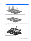
c. Flex the outside bottom of the bezel until it disengages from the display enclosure (3).
d. Lift the bottom corners of the bezel until they disengage from the display enclosure (4).
92 Chapter 4 Removal and replacement procedures