


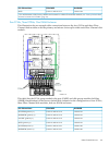

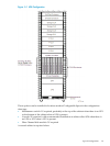
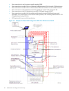
5 Hardware Configuration in Modular Cabinets
This chapter shows locations of hardware components within the 42U modular cabinet for a
NonStop BladeSystem. A number of physical configurations are possible because of the flexibility
inherent to the NonStop Multicore Architecture and ServerNet network.
NOTE: Hardware configuration drawings in this chapter represent the physical arrangement
of the modular enclosures but do not show PDUs. For information about PDUs, see “Power
Distribution Units (PDUs)” (page 42).
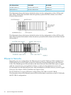
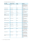
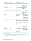
Maximum Number of Modular Components
This table shows the maximum number of the modular components installed in a BladeSystem.
These values might not reflect the system you are planning and are provided only as an example,
not as exact values.
8–Processors6–Processors4–Processors2–Processors
1111c7000 enclosure
2222ServerNet switch in
c7000 enclosure
4444IOAM enclosure
1
24242424CLIMs
2
1 The IOAM maximum requires ServerNet High I/O Switches
2 The CLIM maximum requires ServerNet High I/O Switches
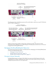
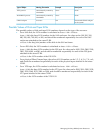
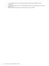
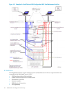
Enclosure Locations in Cabinets
This table provides details about the location of NonStop BladeSystem enclosures and components
within a cabinet. The enclosure location refers to the U location on the rack where the lower edge
of the enclosure resides, such as the bottom of a system console at 20U.
NotesRequired Cabinet (Rack)
Location
Height (U)Enclosure or Component
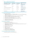
For top feed AC (with and
without the optional UPS).
For bottom feed AC (with
and without the optional
UPS).
AC power cord for the PDU
exiting out the top rear
corner AC power cord for
the PDU exiting out the
bottom rear corner
N/APDUs
The UPS and any ERMs
must be installed in the
bottom U of the rack to
avoid tipping and stability
issues.
Bottom U of rack6UHP R12000/3 UPS
Up to three ERMs can be
installed.
Immediately above UPS
(and first ERM if two ERMs
installed)
3UExtended runtime module
(ERM)
Maximum Number of Modular Components 77