


Hardware options installation 81
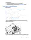
16.
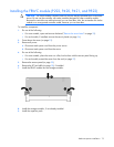
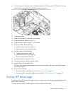
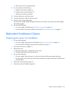
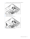
Connect the power cable that came with the RPS option kit (HP part number 676745-001), from the
optional drive cage backplane to the RPS backplane connector.
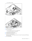
17. Install the fan cage.
18. Install the full-length PCI cards that were removed.
19. Install the system air baffle (on page 30).
20. Install the PCI air baffle (on page 29), if removed.
21. For tower models, do the following:
a. Install the access panel (on page 26).
b. Return the server to an upright position.
22. For rack models, do the following:
a. Install the rack bezel (on page 25).
b. Install the access panel (on page 26).
c. Slide the server back into the rack.
23. Connect each power cord to the server.
24. Connect each power cord to the power source.
25. Press the Power On/Standby button.
The server exits standby mode and applies full power to the system. The system power LED changes
from amber to green.
26. Do one of the following:
o For tower models, install the bezel ("Install the tower bezel" on page 23).
o For rack models, if removed, install the security bezel ("Security bezel option" on page 47).
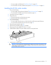
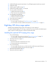
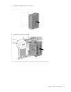
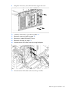
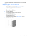
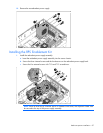
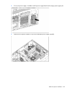
Six-bay LFF drive cage
To install a six-bay, LFF hot-plug drive cage in a server, a Smart array controller option and redundant power
supply option is required.
To obtain the Smart Array controller option, contact an authorized HP reseller.