


1–8 edge switch 2/32 installation guide
Introduction
Each power supply has a separate CTP connection to allow for independent AC power
sources. The power supplies are input-rated at 100 to 230 volts alternating current
(VAC).
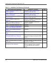
Power supply requirements are listed in Appendix B.
Connectors and Indicators
Connectors and indicators include the:
• Initial machine load (IML) button.
• Ethernet LAN connector.
• Green power (PWR) and amber system error (ERR) LEDs.
• Green and amber status LEDs associated with FRUs.
• RS-232 maintenance port.
Initial Machine Load Button
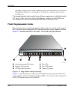
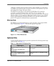
When the IML button, as shown in Figure 1–2 is pressed and held for three seconds,
the switch performs an IML that takes approximately 30 seconds and resets the:
• Microprocessor and functional logic for the CTP and loads firmware from
FLASH memory.
• Ethernet LAN interface, causing the connection to the HAFM server to drop
momentarily until the connection automatically recovers.
• Ports, causing all Fibre Channel connections to drop momentarily until the
connections automatically recover.
An IML should only be performed if a CTP failure is indicated. Do not IML the
switch unless directed to do so by a procedural step or the next level of support. As a
precaution, the IML button is flush mounted to protect against accidental activation.
Ethernet LAN Connector
The front panel provides a 10/100 megabit per second (Mbps) RJ-45 twisted-pair
connector, as shown in Figure 1–2 that attaches to an Ethernet LAN to provide
communication with the HAFM server or an SNMP management workstation. Two
green LEDs are associated with the LAN connector. When illuminated, the left LED
indicates LAN operation at 10 Mbps, and the right LED indicates LAN operation at
100 Mbps.