


edge switch 2/32 installation guide 1–9
Introduction
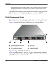
Power and System Error LEDs
The PWR LED, as shown in Figure 1–2 illuminates when the switch is connected to
facility AC power and powered on. If the LED extinguishes, a facility power source,
power cord, or power distribution failure is indicated.
The ERR LED, as shown in Figure 1–2 illuminates when the switch detects an event
requiring immediate operator attention, such as a FRU failure. The LED remains
illuminated as long as an event is active. The LED extinguishes when the Clear
System Error Light function is selected from the Product Manager application. The
LED blinks if unit beaconing is enabled. An illuminated ERR LED (indicating a
failure) takes precedence over unit beaconing.
FRU Status LEDs
Amber and green LEDs associated with switch FRUs provide status information as
follows:
• Port SFP — Amber and green LEDs to the left of the port, as shown in
Figure 1–2 illuminate, extinguish, or blink to indicate various port states
(operational with active Fibre Channel traffic, operational but not communicating,
beaconing, blocked, failed, inactive, or running diagnostics).
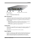
• Fan — An amber LED at the lower left corner of each fan, as shown in Figure 1–3
illuminates if the fan fails or rotates too slowly.
• Power Supply — A green LED at the upper left corner of each power supply, as
shown in Figure 1–3 illuminates if the power supply is operational and receiving
AC power.
Maintenance Port
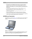
The rear panel provides a 9-pin RS-232 maintenance port, as shown in Figure 1–3 that
provides a connection for a local terminal or dial-in connection for a remote terminal.
Although the port is typically used by authorized maintenance personnel, operations
personnel can use the port to configure switch network addresses.
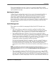
Software Diagnostic Features
The switch provides the following diagnostic software features that aid in fault
isolation and repair of problems: