


Chapter 5 107
Configuration utilities
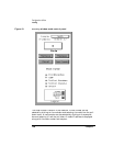
xconfig
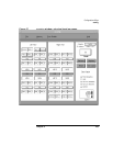
The button boxes are positioned to represent the actual boards as viewed
from the left and right sides. Each of the configurable components of the
node is in the display. The buttons are used as follows:
• Green button—Indicates that the component is present and enabled.
• Red button—Indicates that the component is software disabled in the
system.
• White button—Indicates that it is not possible to determine what the
status of the component would be if POST were to be started.
• Blue box—Indicates that the component is either not present or fails
the power-on self tests.
• Brown button—Indicates that POST had to hardware deconfigure
this component in order to properly execute.
• Grey button—Indicates a hardware component that did not properly
initialize.
The colors are shown in the legend box of the node control panel.
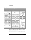
Components can change from enabled to disabled or disabled to
unknown by clicking on the appropriate button with the left mouse
button.
A multinode system requires an additional component on a memory
board to enable the scalable coherent memory interface. This component
can be viewed by right clicking the on the memory board button. The
right mouse button toggles the memory board display between the
memory board and the SCI device
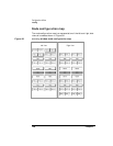
Node control panel
The node control panel allows the user to select a node, select the stop
clocks on an error function, select the boot parameters for a node and
direct data flow between the node and the xconfig utility. It is shown in
Figure 61.