


Chapter 1 13
Overview
V-Class Server Architecture
Each V2500/V2600 I/O port is capable of direct memory access (DMA),
which eliminates processor involvement during data transfers and
streamlines data transfer for large disk blocks and high-speed network
connections.
The PCI bus controllers are numbered based on the V2500/V2600 cabinet
in which they reside. The first component of the hardware path (such as
reported by the HP-UX ioscan utility) indicates which cabinet a
hardware component resides upon.
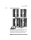
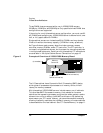
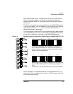
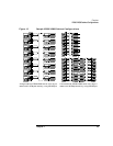
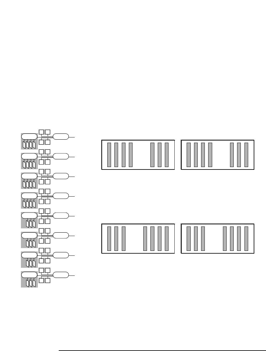
Figure 9 on page 13 shows the PCI bus numbers and card cage locations
for a single-cabinet server. The I/O card cages are accessible from either
the top-left or the bottom-right sides of the V2500/V2600 cabinet.
Figure 9 Numbering and Locations of Single-Cabinet V2500/V2600 PCI I/O
The PCI busses in a single-cabinet server are numbered from 0 to 7, as
shown above. This numbering also is used for the PCI busses in cabinet 0
of a multiple-cabinet server.
0
(to crossbar)
1
2
3
4
5
6
7
6273
0415
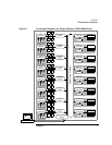
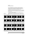
Top left PCI card cage, as viewed from the left side
of the V2500/V2600 cabinet. The PCI bus numbers (1, 5,
0, 4) are shown at the top, and card slots (0–3) are num-
bered in the card cage above.
0123 0123
32103210 210210
012 012
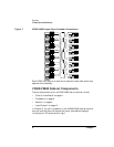
Bottom right PCI card cage, as viewed from the right side
of the V2500/V2600 cabinet. The PCI bus numbers (7, 3,
6, 2)
are shown at the top, and card slots (0–3) are numbered