


28 Chapter 2
Indicators, switches, and displays
System Displays
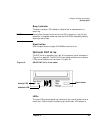
LCD (Liquid Crystal Display)
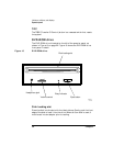
The LCD display is located on the right of the operator panel, as shown
in Figure 17 on page 27. The LCD is a 20-character by 4-line liquid
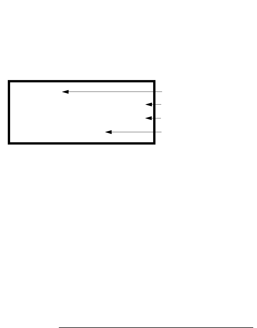
crystal display. Figure 18 shows the display and indicates what each line
on the display means.
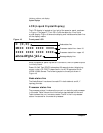
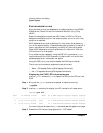
Figure 18 Front panel LCD
When the operator panel key switch is turned on, the LCD powers up but
is initially blank.
Power-On Self Test (POST) takes about 20 seconds to start displaying
output to the LCD. POST is described in the HP Diagnostics Guide:
V2500/V2600 Servers. The following explains the output shown in
Figure 18:
Node status line
The Node Status Line shows the node ID in both decimal and X, Y
topology formats.
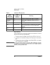
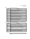
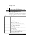
Processor status line
The processor status line shows the current run state for each processor
in the node. Table 3 shows the initialization step code definitions and
Table 4 shows the run-time status codes. The M in the first processor
status line stands for the monarch processor.
MIII IIII IIII IIII
0 (0,0)
IIII IIII IIII IIII
abcedfghijklr
Node status line
Processor status line—lower 16
Processor status line—upper 16
Message display line