


Installing the Fibre Loop Switch
19
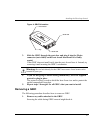
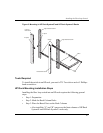
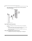
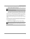
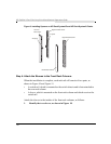
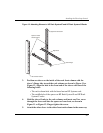
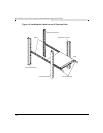
2. Place two barrel nuts on each of the rear rack columns at the holes you
marked, as shown in Figure 7 and Figure 8.
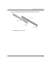
3. For HP Systems racks only, attach one barrel nut to each of the front
rack columns at the holes you marked. For HP Rack System/E and HP
Rack System/U racks do NOT attach barrel nuts to the front columns.
Attach Spacers to HP Rack System/E and HP Rack System/U Racks
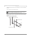
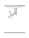
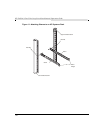
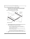
Use the spacers (shown in Figure 9) on HP Rack System/E and HP Rack System/
U Racks only (product numbers J1500A, J1501A, J1502A, J1464A, and
J1466A). Do NOT use them for HP Systems racks (product numbers J1487B and
J1488A).
The spacers are marked “L” and “R” because they differ. Install them inside the
front rack columns. Left and right front rack columns in the instructions below
are as viewed from the rear of the rack.
• Put the “R” spacer on the left front rack column, as shown in Figure 9.
• Put the “L” spacer on the right front rack column, as shown in Figure 9.
Note: Install the barrel nuts with the threaded nut part of the barrel nut on
the inside face of the rack column.
Note: The three holes in the spacer correspond to the three holes in the
EIA unit. Align the middle hole in the spacer with the hole you marked on
the front rack column.