


Installing the Fibre Loop Switch
23
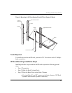
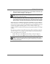
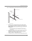
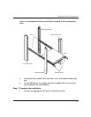
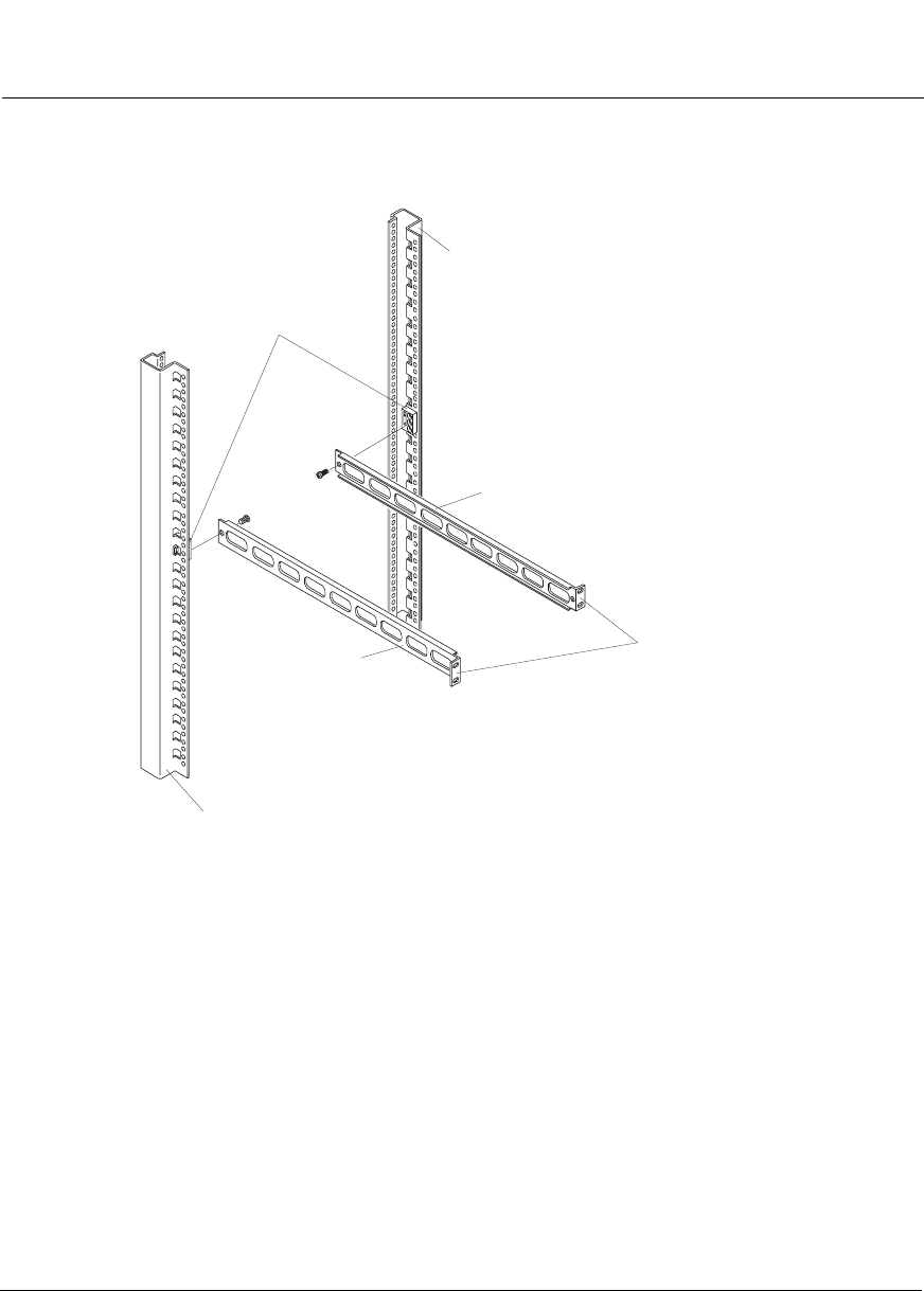
Figure 12: Attaching Sleeves to HP Rack System/E and HP Rack System/U Racks
3. Position one sleeve on the inside of the rack front column with the
sleeve’s flange side toward the rack column, as shown in Figure 11 or
Figure 12. Align the hole in the front end of the sleeve with one of the
following holes:
• The rack column hole with the barrel nut on HP Systems rack.
• The middle hole of the spacer on HP Rack System/E and HP Rack
System/U racks.
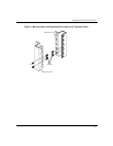
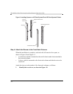
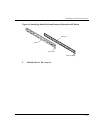
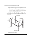
4. Hold the sleeve firmly to the rack column, and insert one Torx screw
through the sleeve and into the spacer or barrel nut, as shown in
Figure 11 or Figure 12. Finger tighten the screw.
5. Attach the other sleeve to the other front rack column in the same way.
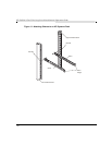
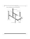
Left Front Rack Column
Right Front Rack Column
Sleeve Flanges
Left Sleeve
Right Sleeve
Spacers on Inside
of Rack Columns