


20
HP P4459A 8-Port Fibre Loop Switch Installation & Operation Guide
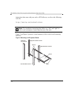
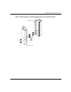
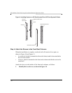
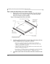
Figure 9: Installing Spacers on HP Rack System/E and HP Rack System/U Racks
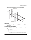
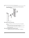
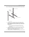
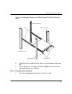
Step 4: Attach the Sleeves to the Front Rack Columns
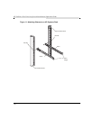
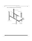
When the installation is complete, each rack rail will consist of two parts, as
shown in Figure 10 and Figure 11:
• A switch rail, which is mounted on the switch chassis and is later attached to
the rear rack column
• A sleeve, which is mounted on the front rack column and which receives the
switch rail
Attach the sleeves to the insides of the front rack columns, as follows:
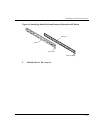
1. Identify the two sleeves, as shown in Figure 10.
Left Front
Rack Column
Left Rear Rack Column
Right Front Rack Column
Right Rear Rack Column
"L" Spacer
"R" Spacer