


24
HP P4459A 8-Port Fibre Loop Switch Installation & Operation Guide
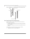
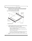
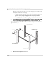
Step 5: Attach the Switch Rails to the Switch Chassis
1. Remove the two side screws (one on each side of the switch chassis)
that retain the cover, as shown in Figure 13. You will not use these
short screws in the rest of this assembly.
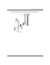
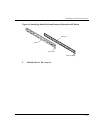
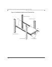
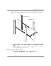
Figure 13: Securing the Switch Rails to the Switch
2. Attach one of the switch rails to the side of the switch chassis with two
of the #1 Phillips-head screws provided, as follows:
• Orient one switch rail against the switch chassis as shown in
Figure 13. The flange on the switch rail is on the outer side of the
switch rail and near the rear panel.
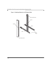
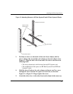
• Align the holes in the switch rail with the screw holes in the switch
chassis as indicated in Figure 13.
• Insert the two #1 Phillips-head screws through the switch rail and into
the switch chassis as shown in Figure 13. Tighten the screws.
3. Attach the second switch rail to the other side of the switch in the same
way.
Switch Rail Flanges
Rear Panel
Switch Rails
Switch
Remove short screw here, and insert
#1 Phillips-head screw provided
Remove short screw
here, and insert #1
Phillips-head screw
provided
Insert #1 Phillips-
head screw provided
Insert #1 Phillips-head screw provided