


HP OmniBook 4100/4150 Removal and Replacement 2-1
2
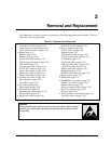
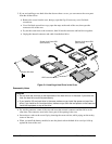
Removal and Replacement
This chapter tells you how to remove and replace the following components and assemblies. The ones
marked by
• are user-replaceable.
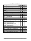
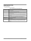
Table 2-1. Removal Cross-Reference
Air vent cover (table on page 2-33).
Audio jack cover (table on page 2-33).
Audio jack PCA (table on page 2-33).
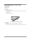
• Battery (page 2-3).
BIOS IC (page 2-28).
Bottom case (page 2-19).
Cable holder (table on page 2-31).
CPU bottom plate (table on page 2-33).
CPU module (page 2-13).
CPU top plate (table on page 2-33).
DC-DC PCA (table on page 2-33).
Display bezel (table on page 2-31).
Display case (table on page 2-31).
Display latch (table on page 2-31).
• Docking door (table on page 2-8).
End cap (table on page 2-31).
Fan (table on page 2-33).
• Foot (table on page 2-8).
Frame (table on page 2-33).
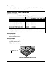
• Hard disk drive (page 2-5).
Heatsink parts (table on page 2-33).
Hinge (table on page 2-31).
• Hinge cover (table on page 2-8).
Inverter PCA (table on page 2-31).
• I/O door (table on page 2-8).
IR PCA (table on page 2-33).
Keyboard (page 2-9).
LCD brackets (table on page 2-31).
LCD flex cable (table on page 2-31).
LCD module (page 2-13).
LCD shield (table on page 2-31).
LED strip cable (table on page 2-31).
LVDS PCA (table on page 2-33).
Module latch (table on page 2-33).
Motherboard (page 2-19).
PCMCIA socket (table on page 2-33).
• Plug-in module (page 2-3).
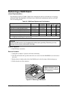
• RAM board (page 2-4).
• RAM/BIOS cover (table on page 2-8).
Speaker cover (table on page 2-33).
Speaker (table on page 2-33).
Spring, grounding (table on page 2-33).
Strip cover (table on page 2-32).
Top case (page 2-16).
• VGA connector cover (table on page 2-8).
VGA PCA (table on page 2-33).
Caution
Always provide proper grounding when performing repairs. Without proper
grounding, an electrostatic discharge may damage the OmniBook and its
components.