


HP OmniBook 4100/4150 Removal and Replacement 2-33
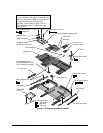
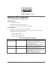
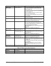
Table 2-11. Removing Bottom Case Components
Component Removal Procedures Additional Steps (See figures on pages 4-2, 4-8)
Air Vent Cover
Plug-in module (page 2-3).
Hard drive (page 2-5).
Keyboard (page 2-9).
Display (page 2-11).
Top case (page 2-16).
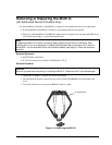
1. Remove the screw from the plastic heat exchange
cover and remove the cover.
2. Lift off the fan and move it aside.
3. For a 2-screw CPU top plate, remove the screw
from the heatsink cover and remove the cover.
4. Remove the 2 or 5 screws from the CPU top plate
and remove the plate.
5. Remove the screw holding the left frame to the
motherboard and lift off the frame.
6. Lift out the air vent cover.
Audio Jack Cover
Plug-in module (page 2-3).
Hard drive (page 2-5).
Keyboard (page 2-9).
Display (page 2-11).
Top case (page 2-16).
1. Remove the screw from the IR PCA and move the
PCA aside.
2. Remove the two screws from the right frame and
remove the frame.
3. Lift the front-right corner of the motherboard slightly
and remove the audio jack cover.
Audio Jack PCA
Plug-in module (page 2-3).
Hard drive (page 2-5).
Keyboard (page 2-9).
Display (page 2-11).
Top case (page 2-16).
1. Remove the screw from the IR PCA and move the
PCA aside.
2. Remove the two screws from the right frame and
remove the frame.
3. Unplug the DC-DC PCA.
4. Unplug the audio jack PCA.
During installation, the metal shield goes under the
motherboard.
BIOS IC
See page 2-28.
Bottom Case
See page 2-19.
CPU Bottom Plate
Keyboard (page 2-9).
CPU module (page 2-13).
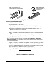
Reassembly Notes: For an OmniBook with a 2-screw
top plate, assemble the CPU module, top plate, and
bottom plate before installing them on the
motherboard.
For an OmniBook 4150† with a 5-screw top plate,
assemble the only CPU module and bottom plate
before installing them on the motherboard.
CPU Module (MMO)
See page 2-13.
CPU Top Plate
Note: For the
OmniBook 4150B, see
“Heatsink/Top Plate”
below.
Keyboard (page 2-9). 1. For an OmniBook 4150† with a 2-screw top plate,
remove the screw from the heatsink cover and lift it
off the heatpipe.
2. Remove the 2 or 5 screws holding the CPU top
plate.
3. Remove the top plate.
Caution: Replace the top plate with one that is
compatible with the CPU module—see the table on
page 4-3.
Caution: Install conductive tape grounding straps and
conductive pads on top of the top plate—just as on the
original top plate.
Caution: For an OmniBook 4100, install a square top-
plate spacer on top of the top plate at the right-rear
corner. (Service note 4100-03C.)