


HP OmniBook 4100/4150 Removal and Replacement 2-35
Component Removal Procedures Additional Steps (See figures on pages 4-2, 4-8)
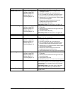
Module Latch, Left
Plug-in module (page 2-3).
Hard drive (page 2-5).
Keyboard (page 2-9).
Display (page 2-11).
Top case (page 2-16).
1. Remove the 1 or 2 screws holding the heat
exchange cover/fan.
2. Lift off the cover/fan and move them aside.
3. For a 2-screw CPU top plate, remove the screw
from the heatsink cover and remove the cover.
4. Remove the 2 or 5 screws from the CPU top plate
and remove the top plate.
5. Remove the screw holding the frame to the
motherboard and remove the frame.
6. Lift off the latch and spring.
Reassembly Notes: See the picture on page 2-28.
Module Latch, Right
Plug-in module (page 2-3).
Hard drive (page 2-5).
Keyboard (page 2-9).
Display (page 2-11).
Top case (page 2-16).
1. Remove the screw from the IR PCA and move the
PCA aside.
2. Remove the two screws from the right frame and
remove the frame.
3. Lift off the latch and spring.
Reassembly Notes: See the picture on page 2-28.
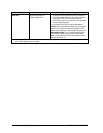
Motherboard
See page 2-19.
PCMCIA Socket
Keyboard (page 2-9). Remove the four screws from the PCMCIA socket and
unplug it from the motherboard.
Speaker, Left
Plug-in module (page 2-3).
Hard drive (page 2-5).
Keyboard (page 2-9).
Display (page 2-11).
Top case (page 2-16).
1. Remove the 1 or 2 screws holding the heat
exchange cover/fan.
2. Lift off the cover/fan and move them aside.
3. For a 2-screw CPU top plate, remove the screw
from the heatsink cover and remove the cover.
4. Remove the 2 or 5 screws from the CPU top plate
and remove the top plate.
5. Remove the screw holding the frame to the
motherboard and remove the frame.
6. Unplug the speaker wires and remove the speaker.
Speaker, Right
Plug-in module (page 2-3).
Hard drive (page 2-5).
Keyboard (page 2-9).
Display (page 2-11).
Top case (page 2-16).
1. Remove the screw from the IR PCA and move the
PCA aside.
2. Remove the two screws from the right frame and
remove the frame.
3. Unplug the DC-DC PCA.
4. Unplug the speaker wires and remove the speaker.
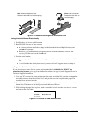
Speaker Cover
On the front corner of the case, slide the latch forward.
Then slide the speaker cover forward slightly, swing it
outward about 2 cm, then pull firmly until it unsnaps
from the case.
Reassembly Notes: If the slider came off the latch,
attach it to the latch before you install the cover.
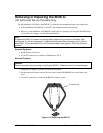
Spring, Grounding
Display (page 2-11). Remove the spring form the hole at the back of the left
or right frame.