


iv HP OmniBook 4100/4150
Figures
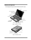
Figure 1-1. OmniBook - Front View....................................................................................................1-3
Figure 1-2. OmniBook - Side View .....................................................................................................1-3
Figure 1-3. OmniBook - Rear View.....................................................................................................1-4
Figure 1-4. Replaceable Module Diagram .........................................................................................1-14
Figure 2-1. Removing the Battery or Plug-In Module..........................................................................2-3
Figure 2-2. Removing a RAM Board...................................................................................................2-4
Figure 2-3. Removing the Hard Disk Drive .........................................................................................2-5
Figure 2-4. Installing a Hard Drive in the Cover..................................................................................2-6
Figure 2-5. Removing the Keyboard....................................................................................................2-9
Figure 2-6. Removing the Display .....................................................................................................2-11
Figure 2-7. Removing the LCD Module ............................................................................................2-15
Figure 2-8. Removing the Top Case...................................................................................................2-17
Figure 2-9. Removing the CPU (OmniBook 4150†)..........................................................................2-21
Figure 2-10. Inserting the CPU (OmniBook 4100/4150†).................................................................2-22
Figure 2-11. Positioning Thermal Pads..............................................................................................2-23
Figure 2-12. Removing the Motherboard...........................................................................................2-26
Figure 2-13. Installing Docking Doors and Module Latch.................................................................2-28
Figure 2-14. Example of Serial Number Label ..................................................................................2-28
Figure 2-15. Removing the BIOS IC..................................................................................................2-29
Figure 2-16. Boot-Block Jumper........................................................................................................2-31
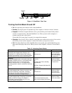
Figure 3-1. Basic Troubleshooting Steps .............................................................................................3-2
Figure 3-2. OmniBook Diagnostic Screens — Basic and Advanced.................................................3-13
Figure 3-3. Serial and Parallel Loopback Connectors........................................................................3-15
Figure 4-1. Exploded View..................................................................................................................4-2
Figure 4-2. Display Components..........................................................................................................4-7
Figure 4-3. Motherboard Components .................................................................................................4-8
Tables
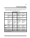
Table 1-1. Product Comparisons..........................................................................................................1-1
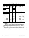
Table 1-2. OmniBook 4100/4150 Series Models.................................................................................1-2
Table 1-3. Activating Power Modes.....................................................................................................1-4
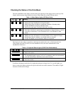
Table 1-4. Main Status Lights (LED Strip Cable)................................................................................1-5
Table 1-5. Keyboard Status Lights (VGA PCA or Motherboard)........................................................1-5
Table 1-6. Fn Hot Keys ........................................................................................................................1-6
Table 1-7. System Interrupts ................................................................................................................1-7
Table 1-8. System Memory..................................................................................................................1-7
Table 1-9. System Input/Output Addresses (100-3FF).........................................................................1-8
Table 1-10. DMA Channels.................................................................................................................1-8
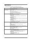
Table 1-11. OmniBook 4100/4150 Series Specifications ....................................................................1-9
Table 1-12. OmniBook 4100/4150 Series Accessories......................................................................1-12
Table 1-13. Functional Structure........................................................................................................1-15
Table 2-1. Removal Cross-Reference...................................................................................................2-1
Table 2-2. Required Equipment ...........................................................................................................2-2
Table 2-3. Recommended Screw Torques............................................................................................2-2
Table 2-4. RAM Board Replacement Part Numbers............................................................................2-4
Table 2-5. Hard Disk Drive Replacement Part Numbers.....................................................................2-5
Table 2-6. Replacing Small Parts (User-Replaceable).........................................................................2-8
Table 2-7. Display Component Compatibility....................................................................................2-13
Table 2-8. CPU Component Compatibility........................................................................................2-19