


only one network connection is active at a time. If the active network connection fails, the IP
address is automatically moved to the surviving network connection.
• At a minimum, the storage system requires one Fibre Channel (or iSCSI) connection from a
host computer to a controller node. HP recommends separate connections from each host
computer to each of the controller nodes in the storage system, with connections distributed
evenly across all nodes.
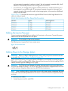
Table 6 (page 35) describes the maximum supported Fibre Channel cable length based on the
cable size and port speed.
Table 6 Cable Limitations for Fibre Channel Host Connectivity
Cable Length LimitSpeedCable Size
100 meters2 Gbps62.5 micron
70 meters4 Gbps62.5 micron
300 meters2 Gbps50 micron
150 meters4 Gbps50 micron
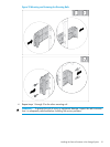
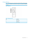
Cabling the Service Processor
Connect a customer-supplied Ethernet cable to the lowest port on the server. Connect the power
cable to PDU, but do not power on at this point.
WARNING! Do not power on the service processor.
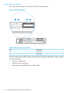
The following icon is typical, but it can vary by server.
Figure 33 Connection Icon
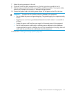
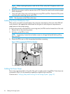
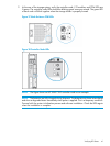
Cabling Power to the Storage System
WARNING! Before you begin cabling the power cords, verify your power connections are set
up correctly. See “Verifying Power Connections” (page 37).
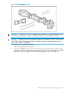
When routing PCM power cords, ensure power redundancy is maintained by connecting each
PCM within a shelf to a different PDU. When observed from the rear, the left side cabling (ID #0)
is black, and the right side cabling (ID #1) is gray.
WARNING! The PCM latch can damage any cables that are routed in such a way that when
the PCM latch handle is closed, it will cut into any cable that becomes wedged between the latch
and the rack post. Keep the cables clear from the PCM latch mechanism.
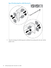
NOTE: When installing cabling, ensure clear access to all storage system components. All power
cords need to be tied and kept behind the rail column in order to access the components during
servicing.
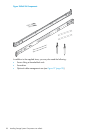
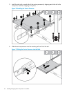
To cable the power cables:
1. Locate the power cord for each PCM.
Cabling the Service Processor 35