


Overview of Installation and Configuration
Configuration Process
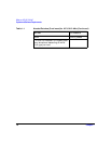
Chapter 226
Configuration Process
Following are the steps to configure HP-UX VLANs. These steps are for
defining VLAN membership, assigning names, VLAN IDs, and port
assignments. This procedure assumes that the switches can add VLAN
tags:
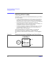
1. Determine the network topology affected. Either draw the affected
network topology or list it. Include all affected end
stations--workstations and servers.
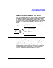
2. Define the VLANs. Decide, according to your requirements, which
systems belong to which logical groups.
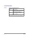
3. Assign VLAN IDs to each VLAN. Ensure that the assignments are
consistent across endstations and switches; otherwise, stations will
not communicate with each other. A VLAN ID can be any number
between 0 and 4094 that is used only once within that port.
NOTE The VLAN ID is not the same as the number of VLANs supported
--HP-UX supports up to 1024 VLANS per LAN card port.
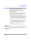
4. Determine which LAN card ports need tagged VLANs and which do
not. Typically, you may need to put a server LAN card port in several
VLANs while a desktop LAN card port can belong to just one VLAN.
5. Assign VLAN IDs to each LAN card port on end stations and
switches. Mark VLANs on the switches as tagged or untagged
according to the LAN card port to which they are connected.
6. On HP-UX servers that must belong to several VLANs, create
VLANs on the corresponding LAN card ports.