


Model 3555B Section III
when no input signal is present and a mechanical zero
adjust is not required. The actual input level to the set is
the algebraic sum of the black dBm meter scale and black
RANGE setting. For example, RANGE is set to 40dBm
and the meter indicates -6.3dBm. The input level is then (-
40) + (-6.3) = -46.3dBm. If the RANGE switch is at
+20dBm and the meter indication is 4.7dBm, the level is
(+20) + (4.7) = +15.3dBm.
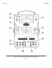
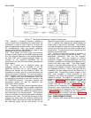
3-24. All panel markings corresponding to the proper
dBm markings on the RANGE switch and meter face are in
black, as is the TMS position of the INPUT switch. The
blue markings correspond to the settings for noise
measurements as discussed in paragraph 3-28. The
response of the meter rectifier circuit is RMS which allows
the set to measure the true power of any arbitrary input
waveform provided the crest factor does not exceed 4:1.
Crest factor is defined as the ratio of the peak value of the
waveform to the RMS value of that waveform. In most
telephonic measurements, consideration of this crest
factor is not necessary.
3-25. The balanced input to the set is achieved through
the use of two repeat coils, one for voice frequencies from
20Hz to 20kHz and the other for carrier frequencies from
10kHz to 600kHz. The maximum high frequency range is
achieved through the use of the 75 ohm functions and the
75 ohm jack. This input bypasses both input repeat coils,
thus allowing measurements from 30Hz to 3MHz. This
high frequency range is limited to 600kHz on the +20 and
+30dBm ranges. The maximum longitudinal input voltage
is 150 volts peak between tip and ring and 200 volts rms at
60Hz between either tip or ring and ground.
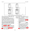
3-26. The switch marked RESPONSE determines the
speed of the meter response and is usually left in the
NORM position for transmission measurements.
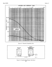
3-27. The jack marked DC MON accepts a Western
Electric 310 or 347 plug with connections to the tip and
sleeve. The dc voltage supplied by this jack can be used
to operate a dc potentiometric recorder requiring 1V or a
dc galvanometric recorder requiring 500uA. The dc output
is proportional to input level on any one range and not
meter deflection since the meter is logarithmically scaled.
Knowing the current required to drive the recorder full
scale and the input impedance of the recorder, enter these
numbers into the recorder compatability chart Figure 3-4 to
determine if the recorder is suitable for use with this set. If
these numbers do not fall within the compatability area,
refer to Paragraph 3-41. Connect an input voltage to the
set and adjust the RANGE switch until a near full scale
indication is observed on the meter. Connect the recorder
plug with the tip negative to the DC MON jack and adjust
the input level until the meter indicates 0dBm. Mark this
point, which should be near full scale, on the recorder
paper. Decrease the input level until the meter indicates -
1dBm. Mark this point on the recorder paper. Continue
until the recorder has been calibrated for each major dBm
division on the meter. The actual input level to the set as
indicated on the recorder will be the algebraic sum of the
RANGE.
3-28. NOISE MEASUREMENT.
3-29. One of the primary functions of this set is to
measure message circuit noise, both metallic and noise-to-
ground. The weighting filters built into this set are switch
selected and their characteristics conform to the standards
set up by the Bell System and Edison Electric Institute.
3-30. In general, noise-metallic measurements are made
by connecting the circuit under test to the INPUT jacks
with a suitable patch cord, selecting the proper bridging or
terminate condition and impedance, selecting the proper
weighting filter and operating the RANGE switch to provide
an on-scale meter indication. Noise measurements
involve many of the same operations as the level
measurements discussed in Paragraph 3-14 and only the
differences will be discussed.
3-31. Four filters are supplied for noise measurements;
C-MESSAGE and 3kHz FLAT for message circuit noise
measurement, a PROG and 15kHz FLAT for broadcast
studio-transmitter links and telephone company program
circuits. These filters are necessary to allow the
measuring set to approximate the response of the human
ear and give an indication representative of a person's
subjectiveness to noise. The frequency response of these
filters is shown in Figures 4-5 and 4-6.
3-32. Once a circuit has been connected, the RANGE
switch is adjusted until the noise fluctuations appear on-
scale on the meter with normal response, and a two-to-
three minute observation of the pointer fluctuations is
made to establish the point at which the pointer appears
most of the time, disregarding the occasional high peaks.
For rapidly fluctuating noise such as atmospheric static or
switching noise, operate the RESPONSE switch to DAMP.
In this position of the switch, the level of the most
frequently occurring peaks should be read. Noise is
specified in dBm (decibels above reference noise) and the
type of filter used is noted, for example, dBmC meaning
C-message weighting is used.
3-33. The noise-metallic level is the algebraic sum of
the indication on the blue dBm meter scale and the blue
dBm RANGE switch setting. For example, RANGE is set
to 20dBm and the meter indicates +7dBm. The noise-
metallic level is (20) + (+7) = +27dBm. The RANGE
switch marking indicates the level at the 0dBm mark on
the left end of the meter scale.
3-34. Occasionally other message circuit weightings
such as the older Bell System F1A weighting or the
International Telecommunication Union's CCITT or
psophometric weighting may be required. To convert from
C-message to F1A, subtract 6dBm from the C-message
indication. The units for F1A weighting are dBa, meaning
decibels adjusted. To convert from C-message to CCITT
or psophometric weighting, subtract 1dBm from the C-
message level as read on the black dBm meter scale and
RANGE switch setting. This will give the noise level in
dBm which is acceptable for psophometric measurements.
3-7