


Model 3555B Section V
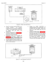
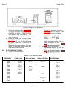
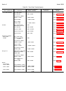
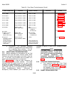
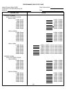
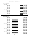
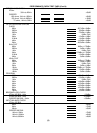
Table 5-6. Front Panel Trouble Analysis (Cont'd)
3555B SHOULD INDICATE SET ACTUALLY CORRECTIVE
INPUT CONDITIONS FUNCTION (RANGE + METER)* INDICATES ACTION
LEVEL -30dBm Change RANGE to -30dBm -30dBm ±0.2dBm See Paragraph 5-35
LEVEL 40dBm Change RANGE to 400dBm -40dBm ±0.2dBm See Paragraph 5-35,
Table 5-9
LEVEL -500dBm Change RANGE to -50dBm -50dBm ±0.2dBm See Paragraph 5-35,
Table 5-9
LEVEL -60dBm Change RANGE to -60dBm -60dBm ±0.2dBm See Paragraph 5-35,
Table 5-9
LEVEL -70dBm Change RANGE to -70dBm -70dBm ±0.2dBm See Paragraph 5-35,
Table 5-9
LEVEL -80dBm Change RANGE to -80dBm -80dBm ±0.2dBm See Paragraph 5-35,
Table 5-9
LEVEL 0dBm RANGE to 0dBm 0dBm
INPUT: TMS, TERM Measure 270mV ac
±0.2dBm at
AC MON jacks See Paragraph 5-38
NG CHECK
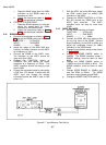
75 UNBAL, Connect RANGE: 0dBm Adjust oscillator
UNBAL signal FUNCTION: VF/Nm level for 0dBm
between tip and ring 600 BAL on 3555B meter
Change input Depress NG button -40dBm Refer to Table 5-8
connection. Connect Change RANGE to 40dBm
signal between tip
and ring and sleeve *Some meter jitter may
(tip and ring shorted be experienced, but the
together), ground reading should be within
lead to sleeve the tolerance indicated.
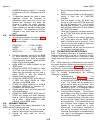
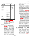
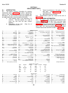
c. Schematics-- The schematic diagrams
contain dc voltage levels and signal levels
for a specified input condition. This will
assist in troubleshooting individual circuits.
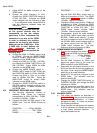
5-31. FRONT PANEL TROUBLESHOOTING.
5-32. Before attempting to troubleshoot the set, first
determine from the front panel controls exactly which
functions are performing properly and which ones are
not. In this way, many troubles can be isolated to a
specific area and sometimes to a component.
5-33. Table 5-6 is a step by step procedure for
checking out the front panel controls. This table
indicates what the results should be for each check
along with the specified tolerance. A space is provided
to enter your results. If these spaces are completed for
each check, they will be of great assistance in making
further troubleshooting checks. Whenever a
discrepancy exists between your results and those
indicated in column 3, refer to the "corrective action"
column.
NOTE
This table is designed to help locate
catastrophic failures. If your set is
only out of the specified tolerances,
a complete adjustment and
calibration procedure should be
performed as described in Paragraph
5-14.
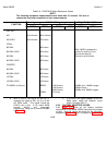
5-34. FUNCTION TROUBLESHOOTING.
a. First determine from the Front Panel
Analysis chart (Table 5-6) exactly which
function is defective. Refer to Table 5-7 for
the probable cause of the malfunction in
the FUNCTION switch assembly.
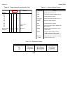
5-35. RANGE TROUBLESHOOTING.
5-13