


Section V Model 3555B
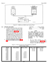
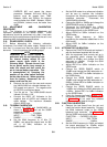
Figure 5-3. +20dBm and +30dBm Level Accuracy Check
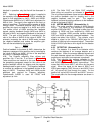
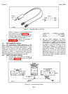
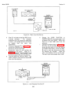
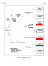
5-10. RETURN LOSS CHECK.
a. To make a return loss check it will first be
necessary to construct a balanced bridge
utilizing 0.1% resistors for each of the four
3555B impedances. Figure 5-4 shows the
equipment test set-up to be used. For this
check to be meaningful, all test leads
should be kept short. The leads connecting
the 3555B to the bridge should be short clip
leads and should be kept away from each
other and from other leads. Keep all the
instruments away from other instruments
that may be referenced to earth ground.
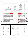
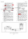
b. Connect the equipment as shown in Figure
5-4 and set the 3555B controls as follows:
FUNCTION..................VF/Nm, 600 BAL
INPUT................................TMS, TERM
RANGE ........................................0dBm
NOTE
The 3555B does not have to be
turned on for this check. If at any
frequency the 3555B return loss
check is out of specification, check
the reference at that frequency as
described in the following
procedure.
c. Set the 654A frequency to 1kHz.
Temporarily close S1 in Figure 5-4 and
adjust the 654A output level for an up scale
indication on the 400FL AC Voltmeter.
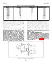
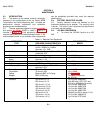
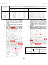
Table 5-4. VF/Nm Level Accuracy Checks 600 BAL and 900 BAL
-80dBm through +30dBm
RANGE 20Hz to 20kHz 40Hz to 15kHz 100Hz to 20kHz 100Hz to 15kHz
+30dBm +30 ±0.5 +30 ±0.2
+20dBm +20 ±0.5 +20 ±0.2
+10dBm +10 ±0.5 +10 ±0.2
0dBm 0 ±0.5 0 ±0.2
-10dBm -10 ±0.5 -10 ±0.2
-20dBm -20 ±0.5 -20 ±0.2
-30dBm -30 ±0.5 -30 ±0.2
-40dBm -40 ±0.5 40 ±0.2
-50dBm -50 ±0.5 -50 ±0.2
-60dBm -60 ±0.5 -60 ±0.2
-70dBm -70 ±0.5
-80dBm -80 ±0.5
5-4