


Model 3555B Section VII
SECTION VII
CIRCUIT DIAGRAMS
7-1. INTRODUCTION.
7-2. This section of the Manual contains circuit
diagrams for the Model 3555B Transmission and Noise
Measuring Set. The functional block diagram (Figure 7-
1) contains signal levels to assist in troubleshooting.
The schematic diagrams (Figures 7-2 through 7-5) show
dc voltage levels which should also aid in locating faulty
components.
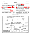
7-3. FUNCTIONAL BLOCK DIAGRAM.
7-4. The functional block diagram (Figure 7-1) of the
3555B serves the dual purpose of showing how various
circuits are arranged to form the set and at the same
time gives voltages and adjustments for use in
troubleshooting the set. This functional block diagram
should be used in conjunction with the troubleshooting
procedure described in Section V.
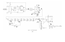
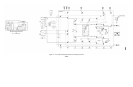
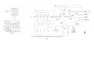
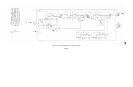
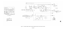
7-5. SCHEMATIC DIAGRAMS.
7-6. The schematic diagrams (Figures 7-2 through 7-
5) contained in this section show the detailed circuits in
the Model 3555B. Components marked with an asterisk
are those that are critical in value. The value of these
components may vary slightly from one set to another
due to variations in transistor Beta etc, and the values
shown on the schematic are average.
7-7. Voltage levels have been included on the
schematics which should greatly assist in
troubleshooting the set. When measuring these
voltages a high input impedance voltmeter (1 megohm
or greater) should be used to prevent circuit loading.
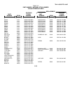
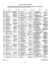
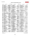
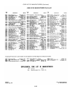
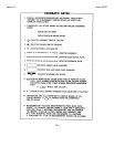
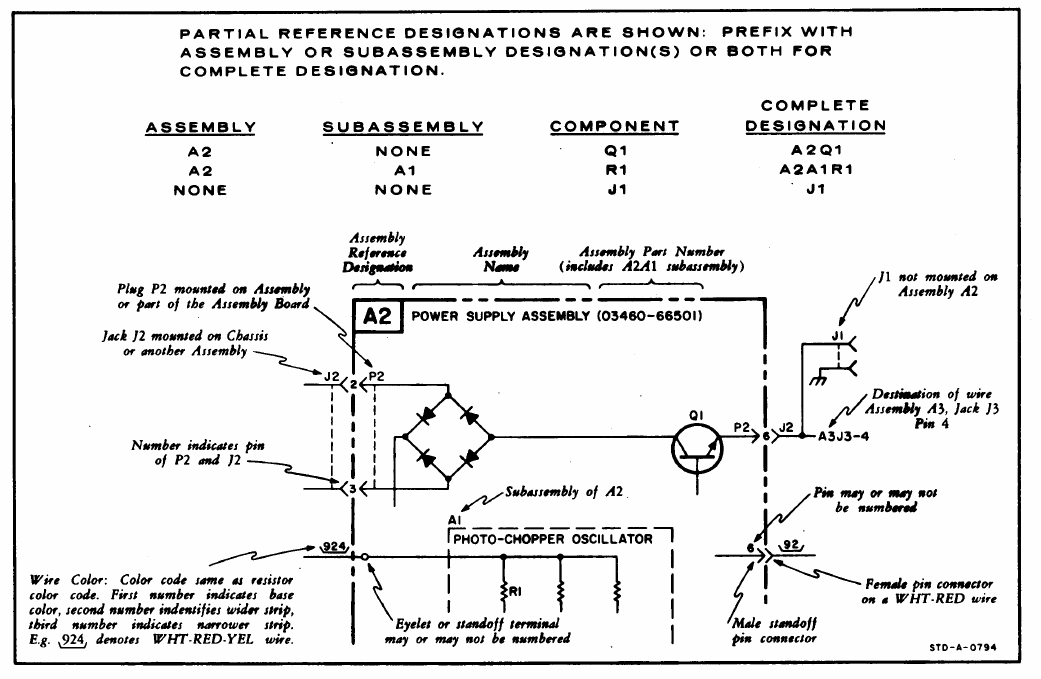
REFERENCE DESIGNATIONS
7-1