


Model 3555B Section V
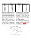
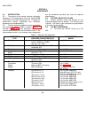
Table 5-2. 75 UNBAL Carrier Accuracy Check
3555B INDICATION (dBm)
RANGE
FREQUENCY
30Hz to 1MHz 100Hz to 600kHz 1MHz to 3MHz
+10dBm +10 ±0.5 +10 ±0.2 +10 ±0.5 ±10% of meter indication in dBm
0dBm 0 ±0.5 0 ±0.2 0 ±0.5 ±10% of meter indication in dBm
-10dBm -10 ±0.5 -10 ±0.2 -10 +0.5 ± 0% of meter indication in dBm
-20dBm -20 ±0.5 -20 ±0.2 -20 ±0.5 ±10% of meter indication in dBm
-30dBm -30 ±0.5 -30 ±0.2 -30 ±0.5 ±10% of meter indication in dBm
-40dBm -40 ±0.5 -40 ±0.2 40 ±0.5 ±10% of meter indication in dBm
-50dBm -50 ±0.5 -50 ±0.2 -50 ±0.5 ±10% of meter indication in dBm
the 3440A/3445A and reconnect the output
of the 654A to the input of the 3555B.
Maintain the 654A meter reference
throughout the remainder of the following
checks.
c. The 3555B meter should indicate 0dBm
±0.1 dBm.
d. Check all the RANGES and frequencies
listed in Table 5-2 for the specified
tolerances. Be sure to maintain the 654A
reference established in step b.
e. Change the 654A to 600 BAL and change
the 3555B to CARRIER, 600 BAL.
Connect the 654A 600 BAL output to the
3555B input using a balanced cable.
f. Check the RANGES and frequencies in
Table 5-3, using the same procedure
described for the 75 UNBAL function.
g. Change the 654A to 135 BAL and change
the 3555B to 135 BAL. Repeat step e for
the same RANGES and tolerances
indicated for the CARRIER 600 BAL
function in Table 5.-3.
h. Change the 3555B to VF/Nm, 600 BAL and
change the 654A to 600 BAL. Check the
+10dBm thru -80dBm ranges in Table 5-4
for the tolerances indicated.
i. Change the 3555B to 900 BAL and connect
a 150 ohm ± 1% resistor in series with each
input lead. Readjust the 654A for 0dBM.
Repeat the checks in Table 5-4 for the
same tolerances.
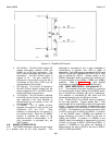
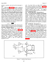
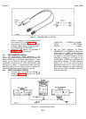
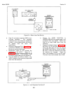
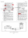
j. To check the top two ranges, connect the
equipment as shown in Figure 5-3 and set
the 3555B controls as follows:
FUNCTION....... VF/Nm 600 BAL
INPUT .................... TMS, TERM
RANGE..........................+20dBm
k. Adjust the 201C for 7.75V on the
3440A/3445A at 100Hz.
l. Tune the 201 C from 100Hz to 20kHz,
maintaining 7.75V on the 3440A/3445A.
Between 100Hz and 15kHz, the 3555B
indication must not change more than
±0.2dBm. Between 15 kHz and 20kHz, the
indication must not change more than
±0.5dBm.
m. Check the +30dBm range using the
procedure described in Steps j through 1,
except change the 3555B range to +30dBm
and change the 201C output level for
24.49V.
n. To check the 900 ohm function on the
+20dBm and +30dBm ranges, connect a
300 ohm +0.1% resistor in series with the
3555B input in Figure 5-3.
o. Change the 3555B to 900 BAL and change
the range to +20dBm.
p. Adjust the 201 C output for 9.49V as
indicated on the 3440A/3445A.
q. Check for the tolerances indicated in Table
5-4 for the +20dBm range.
r. Change the 3555B range switch to +30dBm
and adjust the 201C for 30V on the
3440A/3445A. Check for the tolerances
indicated in Table 5-4 for the +30dBm
range.
Table 5-3. Carrier Level Accuracy
3555B Indication (dBm)
RANGE 135 1kHz -600kHz 10kHz - 300kHz
600 1kHz - 150kHz 10kHz - 100kHz
-50 thru +10dBm ±0.5 ±0.2*
*Increase specification by ±0.3dB on 135 ohms (or 150
ohms) when not battery powered.
5-3