


Model 3555B Section III
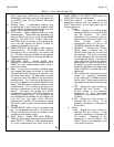
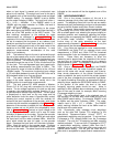
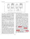
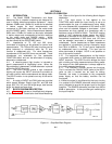
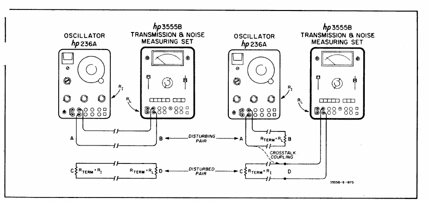
Figure 3-7. Test Setup for Measuring Crosstalk Coupling Loss
3-58. Normally, a frequency selective voltmeter is
used to identify the characteristics of transmission line
interference in order to trace it down to its origin and
apply the appropriate corrective action. As an expedient
for troubleshooting, there are several subjective
measurements that the 236A/3555B can make to help
identify the interference characteristics.
3-59. Since power line noise is the most common
nuisance, a quick check with the 3555B should be made
first. By noting the difference in noise readings between
the 3kHz FLAT and C-message weighted modes, an
indication of line frequency disturbance can be
ascertained if the 3kHz flat mode shows a substantially
higher reading.
3-60. As a further aid in identifying noise, the
lineman's handset can be connected to the AC
MONITOR terminals and an aural analysis made.
Although the handset will not respond to 60Hz, line
interference is usually very rich in odd harmonics and
180Hz can easily be identified. This test also helps to
identify "babble" and other audio frequency interference.
3-61. Vagrant noise, such as atmospheric noise, can
be analyzed by connecting a strip chart recorder to the
DC MONITOR terminals. Long-term seasonal and
temperature effects can also be measured very
conveniently with a recorder.
3-62. Frequency of strong interfering periodic signals,
such as radio transmitters, can be roughly determined
with the 236A and 3555B. The 236A is connected to
one end of the line and the 3555B to the remote end, as
with transmission loss measurements. The oscillator
output is increased until the test meter barely indicates a
signal above the noise. The oscillator frequency is then
changed very slowly while the repairman observes the
3555B for a beat. By tuning for a beat, the frequency of
the interfering signal can be read directly off the
oscillator frequency dial to an accuracy of approximately
±3%. In practice, this measurement would probably be
made using a "loop around" technique. The oscillator
would be connected to a quiet line at the remote location
and this line would be tied to the noisy line back at the
central office. This permits one man to operate both the
oscillator and the test meter.
3-63. When a current flows through a conductor, it
sets up two distinct fields around the conductor - - the
electrostatic (capacitive) field and the magnetic
(inductive) field. Both are capable of inducing
longitudinal voltages in adjacent conductors, and both
increase in proportion to the power and frequency of the
current from which they result. They differ greatly,
however, in how they affect nearby circuits. The voltage
resulting from magnetic induction varies inversely-with
the impedance of the line. That is, the higher the line
impedance, the less voltage that can be induced by a
magnetic field. Capacitively coupled voltage, on the
other hand, increases in direct proportion to line
impedance-- the higher the impedance, the greater the
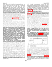
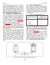
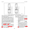
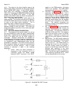
capacitive coupling. By means of a simple test, it is
possible to identify the coupling between two lines, as
shown in Figure 3-8. Since induced voltages are
inversely proportional to line impedance, the voltage
coupled from pair A into pair B (Figure 3-8a) will
increase as the impedance is lowered (i.e., shorted).
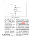
Conversely, since capacitively coupled voltages are
directly proportional to impedance, the coupled voltage
in Figure 3-8b would increase as the impedance is
increased (i.e., open circuited). Both tests in Figure 3-8
should be performed to correlate the result.
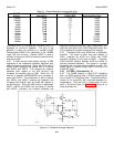
3-64. MEASUREMENTS IN DBC.
3-65. The term dBC means dB Collins and is defined
as
3-11