


Section III Model 3555B
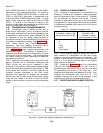
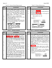
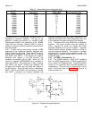
Table 3-5. Noise-to-Ground Measurements
STEP PROCEDURE
1. Turn the 3555B POWER switch to ON and
depress the DIAL/BAT pushbutton. The meter
should indicate in the green BAT GOOD area.
If it does not replace the battery or check the
power source. The battery test operates for
internal battery, office battery or ac power
source.
2. Set the INPUT switch to NOISE BRDG.
3. Select the appropriate weighting filter using
the NOISE WTG switch.
4. Set the RANGE switch to 110dBrn.
5. Depress the NG pushbutton and connect the
set to the circuit to be tested. Down range for
an on-scale indication.
NOTE
Dial and talk may be
accomplished on the metallic
circuit and the connection
held by depressing the HOLD
pushbutton.
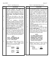
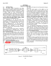
Table 3-7. Recorder Calibration
STEP PROCEDURE
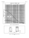
1. Determine the input impedance and full scale
sensitivity of your recorder and refer to
paragraph 3-41 and Figure 3-4 to determine if
your recorder is suitable for use with this set.
The dc voltage supplied by the DC MON 310
jack will drive a dc potentiometric recorder
requiring 1V or a dc galvanometric recorder
requiring 500uA.
2. Connect an input voltage to the set and adjust
the RANGE switch until a near full-scale
indication is observed on the meter.
3. Connect the recorder plug with the tip
negative, to the DC MON jack and adjust the
input level until the meter indicates 0dBm.
Mark this point on the recorder paper which
should be near full scale.
4. Decrease the input level to the set until the'
meter indicates -1dBm. Mark this point on the
recorder paper. Continue this procedure until
every major dBm division on the meter has
been calibrated on the recorder paper.
5. The actual level to the set as indicated on the
recorder is equal to the algebraic sum of the
RANGE setting and recorder indication.
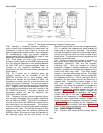
Table 3-6. Balance Measurement
STEP PROCEDURE
1. Perform the Noise-to-ground measurement as
described in Table 3-5.
2. Perform the Noise Metallic measurements as
described in Table 3-4.
3. Compute the line balance in dB using the
results of the above checks.
Balance (dB) = Nm - NG
EXAMPLE:
Noise-to-ground = +26dBrn
Noise Metallic = (-)+90dBrn
Balance in dB = -64dBm
NOTE
The noise-to-ground
measurement above includes
the 40dB correction factor.
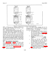
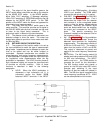
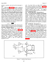
Table 3-8. Transmission Loss Measurement
STEP PROCEDURE
1. For a transmission loss measurement to be
meaningful, it should first be determined if
there are any extraneous signals present that
will affect your measurement. To do this,
connect the measuring set to the circuit and
determine if interfering signals are present.
Levels below 60dB can, in most cases, be
ignored. A butt-in can be connected to the AC
MON jacks to aid in determining the
interfering source.
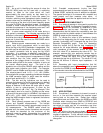
2. Establish a connection like the ones shown in
Figure 3-6.
3. Adjust the oscillator output level for 0dBm.
Measure the level at the receiving end and
record this level.
4. Insertion loss is equal to the difference
between the sending level and the receiving
level, ignoring any extraneous signals.
EXAMPLE:
Sending level = 0dBm
Receiving level = (-)- 20dBm
Insertion loss = 20dB
3-14