


Model 3555B Section V
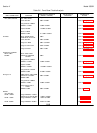
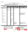
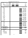
Table 5-8. FUNCTION Switch Resistance Values
NOTE
The following resistance measurements were made with C1 shorted. Be sure to
remove the short after completion of your measurements.
INPUT JACKS DIAL/AC MON JACKS
FUNCTION Tip to Ring Tip to Ground Ring to Ground
BRDG TERM BRDG TERM BRDG TERM
DIAL BAT
NG 80.4 kilohms 80.4 kilohms
NG HOLD 80.4 kilohms 700 ohms
VF/Nm
900 BAL 900 ohms
DIAL JACKS, resistance is
900 BAL HOLD 400 ohms infinite Tip to Ring, Tip to
Ground and Ring to
600 BAL 600 ohms Ground on all functions.
600 BAL HOLD 350 ohms
CARRIER
600 BAL 600 ohms
600 BAL HOLD 600 ohms
135 BAL 135 ohms
135 BAL HOLD 135 ohms
75 UNBAL, to Ground BRDG: 100 kilohms, -30dBm thru +30dBm ranges
120 kilohms, 40dBm Range
400 kilohms, -50dBm thru -80dBm ranges
TERM: 75 ohms
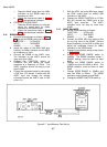
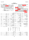
b. With a 6.2mV rms signal at XA3 pin 9,
measure the signal at XA1, pin 6 or at the
AC MON jacks. This signal should be
270mV rms ± l10o. If not, check A3Q6
through A3Q10 and associated
components, using the dc levels indicated
in Figure 7-5.
c. If a 270mV rms signal appears at the AC
MON jacks, check the detector circuit
(A3Q11 through A3Q17).
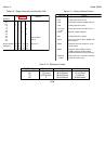
5-39. FACTORY SELECTED VALUES.
5-40. Table 5-11 lists all the factory selected
components in the Model 3555B, along with the purpose
of each. Nominal values are shown on the schematic
diagrams in Section VII and in the parts list, Table 6-1.
5-15