


Section IV Model 3555B
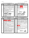
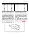
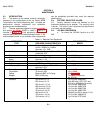
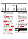
Table 4-1. Range Attenuation and Amplifier Gain
RANGE RANGE ATTENUATOR
Setting Attenuation PADS USED Input Amplifier Gain
+30dBm 80dB 1,2,3 3.6dB
+20dBm 70dB 1,2,4 3.6dB
+10dBm 60dB 1,2 3.6dB
0dBm 50dB 2,3 3.6dB
-10dBm 40dB 2,4 3.6dB
-20dBm 30dB 2 3.6dB
-30dBm 20dB 3 3.6dB
-40dBm 10dB 4 3.6dB
-50dBm 0dB 0 3.6dB
-60dBm 0dB 0 13.6dB
-70dBm 0dB 0 23.6dB
-80dBm 0dB 0 33.6dB
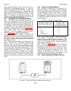
In positions 4 thru 12 (-SODBM thru +30DBM), A3R11 is
bypassed for maximum feedback. The gain of the
amplifier in these nine positions is a constant 2.5dB.
Potentiometer A3R26 is for calibration of the -80DBM
range, 600 ohm function. Resistor A3R27 is used to
maintain a charge on A3C22 to prevent transients when
changing ranges.
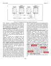
4-23. In order that the meter always indicate in DBM
regardless of the impedance selected, additional gain
switching must be performed. When the 75 function is
chosen, A3K2 energizes and places A3R16 in parallel
with A3R14 and A3R15. This reduces the negative
feedback (with respect to the 600 function) and
increases the amplifier gain by 9dB. When the 135
function is selected, A3R22/R23/R24 are connected in
series with A3R16. This combination is then in parallel
with A3R14 and A3R15, reducing the feedback and
increasing the amplifier gain by 6.4dB with respect to
the 600 function. When the 900 function is depressed,
A3R17, A3R19 and A3R20 are connected in parallel
with A3R13, increasing the negative feedback and
reducing the amplifier gain by 1.7dB. Relays A3K1 thru
A3K3 are controlled by the FUNCTION switch when any
of the impedance functions except 600 are selected.
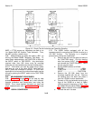
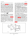
4-24. Transistors A3Q1 and A3Q2 form a differential
amplifier. The signal is taken from the collector of
A3Q1, amplified by A3Q4 and A3Q5 with A3Q5
providing feedback to the base of A3Q2. Transistor
A3Q3 provides isolation between A3Q2 and A3Q4 to
prevent undesired feedback. This results in a greater
bandwidth than could be achieved without its use. The
output signal is coupled through A3R17 and A3C10 to
the INPUT switch.
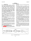
4-25. FILTERS. (Schematic No. 3)
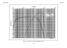
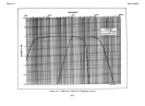
4-26. The 3555B contains a 3kHz FLAT weighting
filter, a C MSG weighting filter, a PROG weighting filter
and a 15kHz FLAT weighting filter. These active filters
consist of five amplifiers with controlled feedback for
waveshaping. They are used in combinations to form
each of the filters (refer to Figure 7-1). Since all of
these amplifiers are
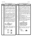
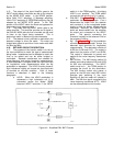
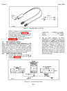
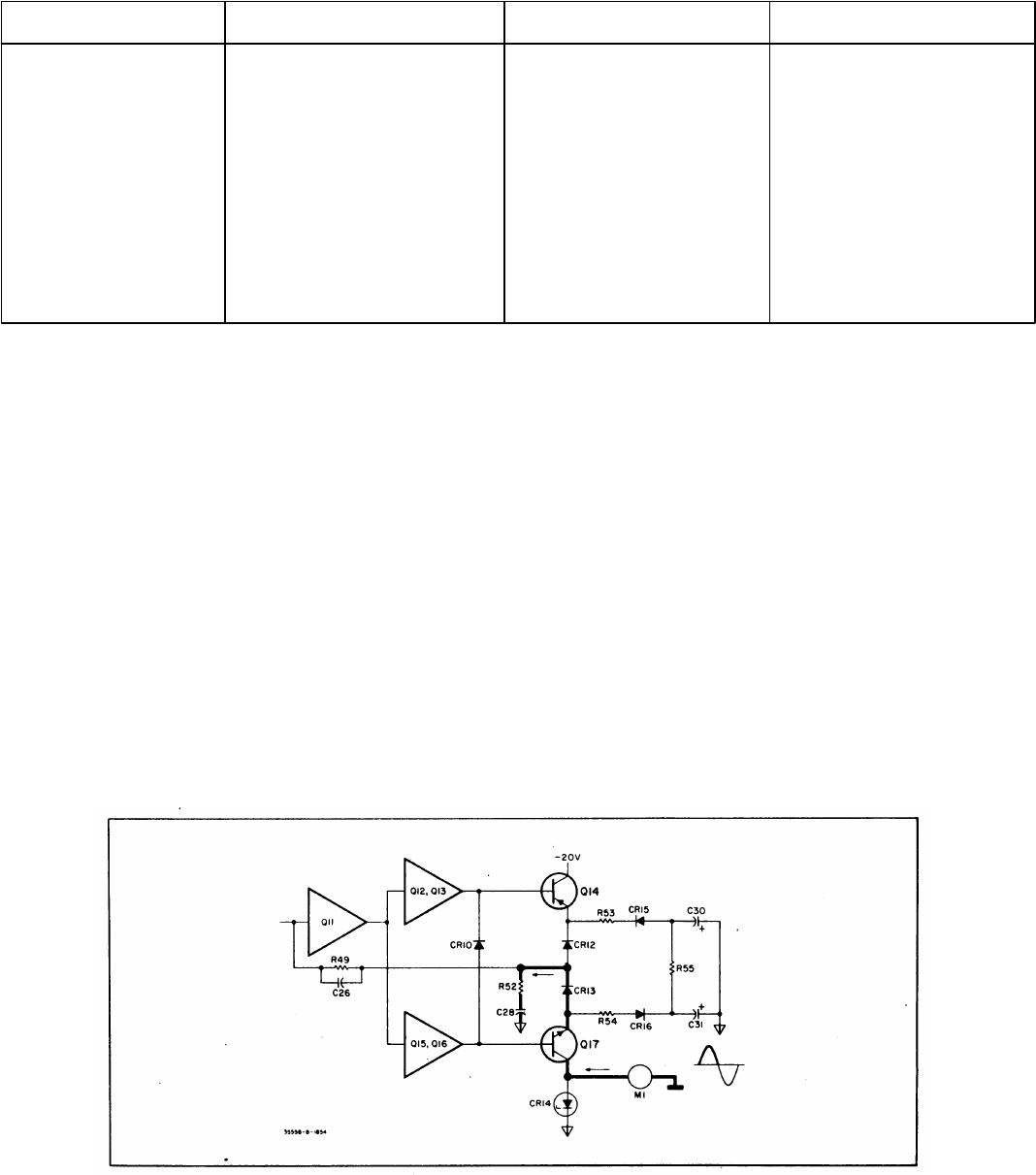
Figure 4-4. Simplified Average Detection
4-4