12 - 8
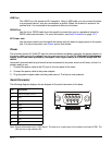
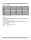
RS232 Pin Configuration
Note: This base cannot be daisy-chained.
Mounting
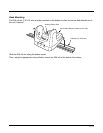
Set the base on a dry, stable surface, such as a desktop or workbench near an electrical outlet. Be sure
to provide enough workspace with good lighting for the user to view and operate the Dolphin terminal
while it is in the base.
When choosing a location, bear in mind that:
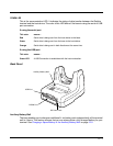
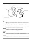
• the mounting location must allow users easy access to the Auxiliary Battery Well, and
• the serial and USB ports as well as the power jack face straight out of the rear panel, and you will most
likely want easy access to them in the future.
Installation Hardware
Screw: 3/16 in. dia x 5/8 in. long pan head screw
Washer: 1/2 in. OD x 7/32 in. ID x 3/64 in. thick
Nut: 3/16 in. dia
Base /Host Port (DCE) IBM AT DB9 (DTE) IBM XT DB25 (DTE) Modem DB25 (DCE)
Pin / Input Signal
2 / (RD) 23 2
3 / (TD) 32 3
5 / (SG) 57 7
4 / (DTR) 420 6
6 / (DSR) 66 20
7 / (RTS) 74 5
8 / (CTS) 85 4


