


25
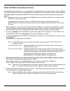
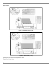
Cable Installation (Secondary Scanner)
The following steps describe how to properly install the cables between a secondary scanner and the MS2420.
The MS2420 and the secondary scanner must then be configured to communicate properly. Cable installation
alone does not guarantee that the MS2420 will communicate properly with the host system and secondary
scanner.
Note: Contact a customer service representative before connecting another manufacturer’s scanner to the
MS2420 as a secondary scanner.
Configuration bar codes are located in the MS2xxx Stratos Series Configuration Addendum
(PN 00-02034x) under Scanner Configuration Bar Codes: Auxiliary Port, Quick Start for a Secondary
Scanners.
1. Refer to pages 18 - 23 for the type of interface (RS232, RS485, etc.) required for the application. Follow
the cable installation steps under the appropriate interface before continuing. Once the communication
and power cables have been installed follow step 2 below for the secondary scanner installation.
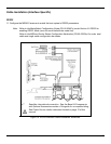
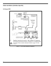
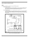
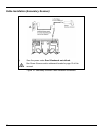
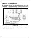
2. Connect the straight end of the RS232 PowerLink AUX cable (PN 57-57099x-3 or PN 57-57099x-3-12)
into the RS232 socket of the secondary scanner (see the figure on page 26).
3. Connect the angled end of the RS232 AUX cable (PN 57-57099x-3 or PN 57-57099x-3-12) into the 10-pin
socket labeled
Aux RS232 In, on the bottom of the MS2420.
Note: The MS2420 series aux port requires the signals; transmit, receive, RTS & CTS from the
secondary scanner.
For Rev G Units or later: The MS2420/MS2430’s auxiliary port will support 5VDC devices with a
700mA maximum current.
For Rev F units or earlier: The MS2420/MS2430’s auxiliary port will support 5VDC devices with a
150mA maximum current. If the auxiliary device exceeds this specification,
an external power supply will be required to power the auxiliary device.
The following Honeywell scanners can receive power from
MS2420/MS2430: the MS9520, MS9540, and the MS5145.
4. This step is required for secondary devices that require >5VDC and/or 700mA current to operate.
Skip to step 5 if the secondary device requires ≤ 5VDC.
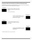
Plug the power supply into the secondary scanner’s PowerLink cable (PN 57-57099x-3 or
PN 57-57099x-3-12) and connect AC power to the secondary scanner.
Note: Check the AC input requirements of the power supply to make sure the voltage matches the AC
outlet. The outlet should be located near the equipment and be easily accessible.
5. Configure the MS2420 and the secondary scanner. The auxiliary input port’s data format must match the
main output format of the secondary scanner.
Note: Refer to the MS2xxx Stratos Series Configuration Addendum (PN 00-02034x) under Scanner
Configuration Bar Codes: Auxiliary Port, Quick Start for a Secondary Scanners.