


24 CMX58886CX cpuModule BDM-610000050 Rev A
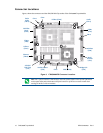
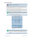
Auxiliary Power (CN3)
Power can be conveyed to the module either through the PCI-104-Plus bus (CN16) or through the Auxiliary
Power connector (CN3). The cpuModule only requires +5 V
DC and ground for operation; however, other
modules in the system may require +12 V
DC, –12 VDC, and –5 VDC. In these instances, the corresponding inputs
on the Auxiliary Power Connector (CN3) may be used to supply these voltages.
Insufficient current supply will prevent your cpuModule from booting. The gauge and length of the wire used
for connecting power to the cpuModule must be taken into consideration. Some power connectors have clip
leads on them and may have significant resistance. Make sure that the input voltage does not drop below +4.8 V
at the +5 V power pins. (Refer to Table 2 on page 10 for the cpuModule’s power requirements). A good rule of
thumb is to use wire that can supply twice the power required by the system.
WARNING If you connect power incorrectly, the module will almost certainly be destroyed. Please verify
power connections to the module before applying power.
Note Connect two separate wires to the +5V pins (2 and 8) on the power connector to ensure a good
power supply connection. We recommend that no less than 18 gauge wire be used and the length of this
wire should not exceed 3 ft. Always measure the voltage drop from your power supply to the power pins
on the cpuModule. The voltage at pins (2 and 8) should be +5V.
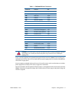
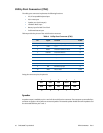
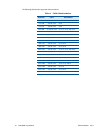
Table 7 Auxiliary Power Connector (CN3)
1
1. For more information on the ATX style signals, +5V Standby and
PSON#, refer to the Power Management section in Chapter 4, Using
the cpuModule.
Pin Signal Function
1 GND Ground
2 +5 V +5 Volts DC
3 +5V_STDBY +5V Standby (ATX)
4 +12 V +12 Volts DC
5 Reserved Reserved
6 –12 V –12 Volts DC
7 GND Ground
8 +5 V +5 Volts DC
9 GND Ground
10 +3.3 V See note below
11 PSON# Power Supply On (ATX)
12 +3.3 V See note below
Note The +3.3 V pins (10 and 12) on the auxiliary power connector (CN3) are connected to the +3.3 V
pins on the PC-104-Plus bus by default. These pins be configured to supply power to PC/104-Plus or
PCI-104 expansion. If +3.3 V is supplied to the PC/104-Plus connector from the onboard power supply,
the +3.3V pins (10 and 12) are not connected. Refer to the B3 description in Table 58 on page 82 for more
information.