


BDM-610000050 Rev A Chapter 3: Connecting the cpuModule 39
multiPort Configured as a Floppy Drive Controller
The multiPort (CN6) can be configured to be a floppy drive controller. This can be configured in the BIOS Setup
under Integrated Peripherals. For more information on configuring the multiPort in the BIOS Setep, refer to
page 60
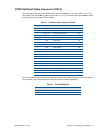
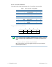
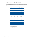
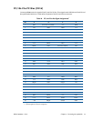
Table 24 shows the pin assignments to connect a floppy drive to the multiPort.
Table 24 multiPort Connector Floppy Pinout (CN6)
1
1. Signals marked with (#) are active low.
CN6 Pin Function DB-25 Floppy Drive Pin
1DS0#1 14
2DR014 2
3INDEX#2 8
2
2. These signals must be pulled to 5V with separate 470 Ohm resistors.
4 HDSEL# 15 32
5 TRK0# 3 26
2
6DIR#16 18
7 WRTPRT# 4 28
2
8 STEP# 17 20
9RDATA#5 30
2
10 GND 18 —
11 DSKCHG 6 34
2
12 GND 19 odd pins
13 — 7 —
14 GND 20 odd pins
15 MTR0# 8 10
16 GND 21 odd pins
17 — 9 —
18 GND 22 odd pins
19 DS1# 10 12
20 GND 23 odd pins
21 MTR1# 11 16
22 GND 24 odd pins
23 WDATA# 12 22
24 GND 25 odd pins
25 WGATE# 13 24
26 +5 V — —