


80 CMX58886CX cpuModule BDM-610000050 Rev A
Jumper Settings and Locations
Many cpuModule options are configured by positioning jumpers. Jumpers are labeled on the board as JP
followed by a number.
Some jumpers have three pins, allowing three settings:
• Pins 1 and 2 connected (indicated as “1–2”)
• Pins 2 and 3 connected (indicated as “2–3”)
• No pins connected
Some jumpers have two pins, allowing two settings:
• Pins 1 and 2 connected (indicated as “closed”)
• Pins 1 and 2 unconnected (indicated as “open”)
Solder jumpers are located on the cpuModule’s bottom side. Solder blobs are factory-set and rarely changed.
Contact RTD Technical Support for further information.
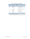
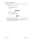
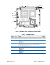
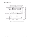
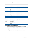
Figure 6 shows the jumper and solder blob locations that are used to configure the cpuModule. In both top and
bottom figures, the PC/104 bus connector is at the six o'clock position. Table 57 lists the jumpers and their
settings. Table 58 lists the solder blobs and their settings.
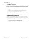
1
2
3
1
2