


BDM-610000050 Rev A Chapter 3: Connecting the cpuModule 47
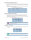
External Power Management (CN12)
An external power management connector (CN12) is available for external devices to wake the system from low
power states. Some low power modes require that +5 V standby power is applied to the cpuModule during the
wake event.
For more information on power management, including a description of the board’s supported wake options,
refer to the Power Management section on page 66.
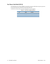
Optional RTC Battery Input (CN13)
The optional RTC battery input is the connection for an external backup battery. This battery is used by the
cpuModule when system power is removed in order to preserve the date and time in the real time clock.
Connecting a battery is only required to maintain time when power is completely removed from the cpuModule.
A battery is not required for board operation.
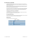
Fan Power, +5 V (CN14)
If a fan is required to cool the cpuModule, it can be wired to CN14, which provides a continuous connection to
+5 V and ground.
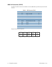
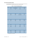
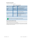
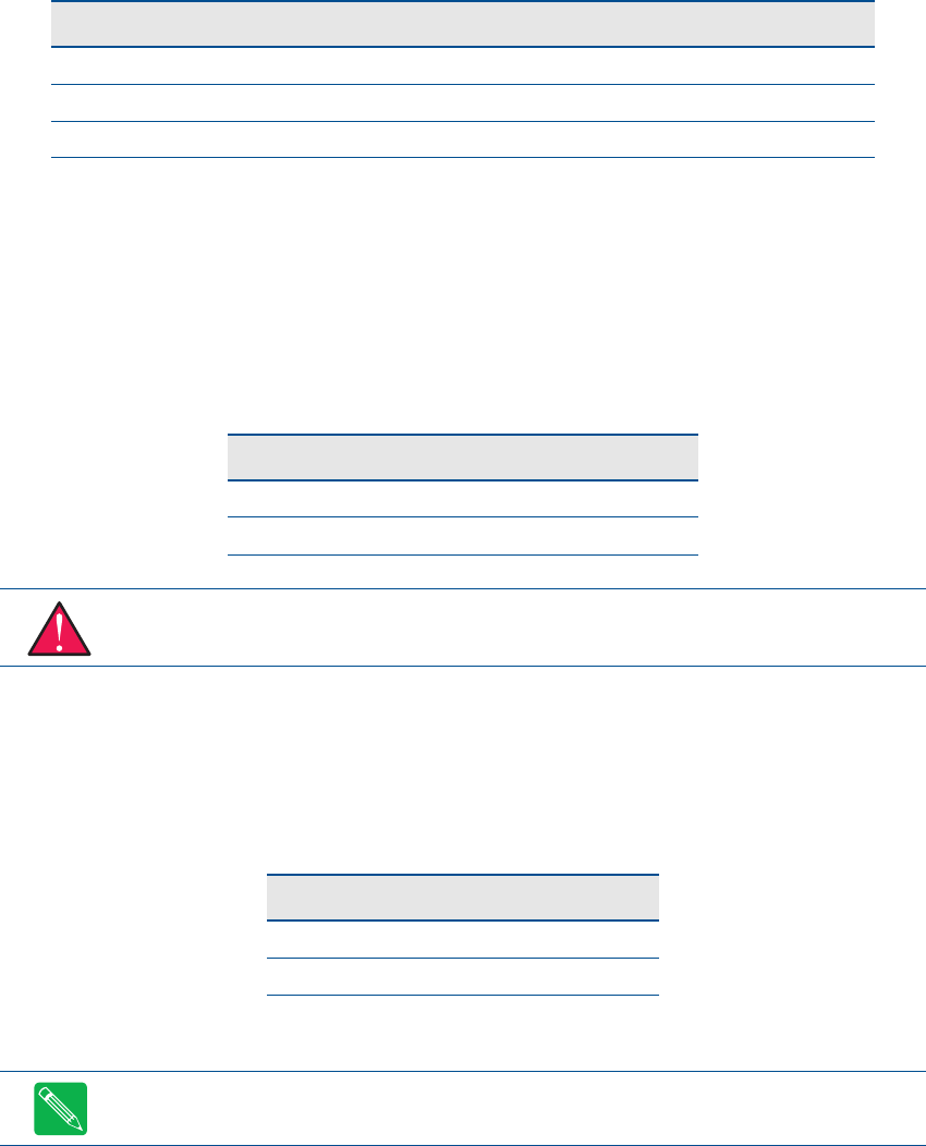
Table 30 External Power Managment (CN12)
Pin Signal Function
1 +5V_STDBY +5 V standby Power
2 GND Ground
2 PME# Powerment Management Event input
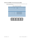
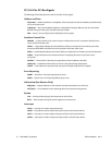
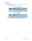
Table 31 Optional RTC Battery Input (CN13)
Pin Signal Function
1 BAT RTC Battery Input
2 GND Ground
WARNING This optional RTC battery connector (CN13) should be left unconnected if the utility port
connector (CN5) has a battery connected.
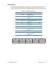
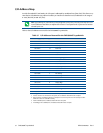
Table 32 Fan Power, +5 V (CN14)
Pin Signal Function
1 +5V +5 Volts DC
2 GND Ground
Note To utilize the thermal fan mode feature in the BIOS, the fan must be connected to CN15