


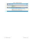

82 CMX58886CX cpuModule BDM-610000050 Rev A
Table 58 CMX58886CX Solder Blobs
Solder
Blob
Positions Function Default
B1 3 Connect the PCI VI/O to either +3.3 V or +5 V
positions 1–2: +5 V
positions 2–3: +3.3 V
pins 2–3
B2 2 Solder closed to connect USB ground to frame ground open
B3 3Solder jumper B3 can connect +3.3 V on the PCI bus to either the onboard +3.3V
or to the board’s +3.3 V supply pins on the auxiliary power connector (CN3).
positions 1–2: connect PCI +3.3 V to CN3, pins 10 and 12
positions 2–3: connect PCI +3.3 V to onboard +3.3 V for powering PC/104-Plus
or PCI-104 expansion cards (current should not exceed 1A)
pins 1–2
B7 2 Solder closed to connect Ethernet ground to frame ground open