


BDM-610000050 Rev A Chapter 4: Using the cpuModule 61
IDE Controller Configuration
The CPU’s onboard EIDE connector (CN10) supports several different drive speed modes, which are BIOS
configurable. Supported drive modes will depend on whether a 40-conductor or 80-conductor cable is
connecting the EIDE device. The modes and cable detection schemes described below may be set in the BIOS
Setup. Similarly, the ATA/IDE Disk Chip socket (U16) is BIOS configurable.
Cable Modes
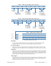
There are two types of cables that may be used for connecting drives to the EIDE connector: 40 conductor cables
or 80 conductor cables. Depending on the cable used, different drive speeds are supported. A 40 conductor cable
can be used for speeds up to UDMA Mode 2 (Ultra ATA/33).
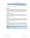
In order to use drive speeds faster than UDMA Mode 2 (Ultra ATA/33), an 80 conductor cable is required. The
BIOS can be configured to detect the presence of an 80 conductor cable. The 80 conductor cable adds a ground
wire between each signal, and uses standard 40 pin connectors, therefore an adapter board is required to connect
an 80 conductor cable to CN10.
Cable Detection
Every time the cpuModule is powered on or a hardware reset is issued, the BIOS will automatically detect the
presense of a 80 conductor cable connecting a device to CN10. The user selectable cable detection modes are
described below.
Device and Host Mode
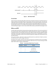
This method involves a capacitor on the PDIAG signal, which has a pull-up connection to a logic 1 voltage. To
determine if the connected cable is 40 conductor or 80 conductor, the CPU first sends a command to the
attached device. When the device receives the command, it asserts the PDIAG signal low, forcing the capacitor
to discharge. The device then deasserts the PDIAG signal, and monitors the charging of the pulled-up capacitor.
If a 40-conductor cable is connected, the signal will still be low when sampled by the device. If an 80-conductor
cable is connected, the capacitor will charge before the device samples PDIAG, and thus read a logic 1. Once the
cable is determined, the device reports the type of cable to the CPU.
Host Determination of Cable Type
For this method of detection, the CPU reads the CPBLID pin, which determines if a 40-conductor or 80-
conductor cable is connected between the CPU and device. The CPBLID signal is pulled low on the CPU end of
the connection by default, indicating that a 40-conductor cable is used if the signal is not driven.
If an 80-conductor cable is connected, the device is able to drive CPBLID high, and the CPU can determine that
an 80-conductor cable is connected. When a 40-conductor cable is used, this pin is not connected, and the CPU
cannot read the the signal driven by the device.
Device Detect
For device detect mode, the CPU issues a command to the device, which tells the CPU the fastest drive speed
mode it can use. The CPU then sets the transfer mode to the fastest speed supported by the device.
WARNING When this cable detection method is enabled, the highest transfer speed supported by the
device will be used regardless of whether a 40-conductor or 80-conductor cable is used. If the device speed
does not match the cable, data corruption and unexpected behaviors may occur. This mode should not
be selected unless the user knows the cable type and the modes supported by the connected EIDE device.