


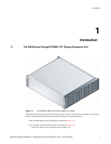

Introduction
IBM System Storage DCS9550 1S1 Storage Expansion Unit Installation, Service, and User Guide 5
Note: * Please contact your supplier for further information.
Important Switch settings are only read at Power On.
1.2.3 SCM Input/Output Module
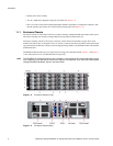
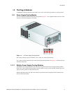
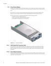
The DCS9550 1S1 Storage Expansion Unit includes an enclosure with rear facing bays which houses one or two
SATA Control Interface Adaptor (SCM I/O) modules (see Figure 1–3), dependent on configuration required.
The plug-in SCM I/O modules have been designed for integration into a DCS9550 1S1 Storage Expansion Unit,
providing external FCAL cable interfacing with up to 16 SATA disk drives.
Processors housed on the SCM I/O modules provide enclosure management and interface to devices on the
Backplane, PSU, SCM and Ops Panel, to monitor internal functions.
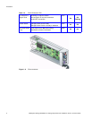
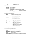
The module incorporates the following LED indicators:
Host
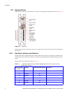
Important If only one SCM module is fitted, the SCM module must be installed in Rear Bay 4 location [see
Figure 1–3, ”Enclosure Chassis (Rear)”, on page 2] and a Blank I/O module fitted in the unused
bay.
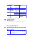
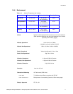
7 & 8
Drive Loop Speed
Select
Sw 7 Sw 8
DCS9550 Controller Settings Off Off Force 1Gb/s
DCS9550 Controller Settings On Off Force 2Gb/s (recommended)
9 & 10
Drive Addressing
Mode Selection
Sw 9 Sw 10
DCS9550 Controller Settings Off On Mode 1
On On Mode 0
On Off Mode 2
Off Off Mode 3 (not supported)*
11
SOFT SELECT On Selects functions using the
hardware switches
12 Not Used Off
Table 1–1 Ops Panel Switch Functions (Default settings for DCS9550 1S1 Storage Expansion
UnitSCM usage at 2Gb/s)
Switch Number
*See Sw 11
Function Recommended Setting Definition
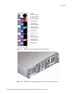
Table 1–2 SCM I/O Module LEDs
LED Definition Color Normal
Status
Fault
Status
FC Host Port 0
Signal Good
Incoming FC signal is GOOD
No connection or incorrect connection
Invalid SFP connection
Green
On
Off
Flashing