Introduction
12 IBM System Storage DCS9550 1S1 Storage Expansion Unit Installation, Service, and User Guide
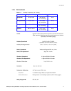
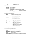
1.4.7 Interfaces
1.4.8 SCM I/O Module Specification
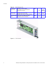
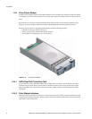
1.4.9 Drive Carrier Module Specification
Please contact your supplier for details of approved drives.
Important Operating the DCS9550 1S1 Storage Expansion Unit with non-approved drives may invalidate the
warranty.
•EMC EN55022 (CISPR - A), FCC A
Drive support See drive carrier specification
Attachment 1 FCAL loop of 16 drives
Passive Backplane with 1 or 2 Loop Resiliency Circuit (SCM) I/O Modules.
Host Port: FC-AL
SFP - SFP cables
Maximum external cable length: see
manufacturer’s specification
Expansion Port: SFP to SFP cables
Speed 1.5Gb/s internal to each drive, 1Gb/s or 2Gb/s external
• Creates connections to a single loop of 16 drives
• 1 External FC loop with two SFP connections
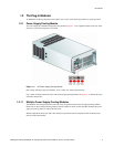
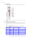
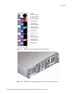
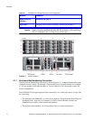
Mounting Rear, single bays 3 and/or 4 (see Figure 1–3)
Connectors • 2 x Expansion Ports: SFP connector
• 2 x Host Ports: SFP connector (2 per port)
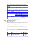
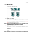
LED Functions
FC Host Port 0 Signal
Good
– Green: On: Incoming FC signal is GOOD
–Off: no connection or incorrect connection
– Flashing: Invalid SFP connection
FC Host Port 1 Signal
Good
– Green: On: Incoming FC signal is GOOD
–Off: no connection or incorrect connection
– Flashing: Invalid SFP connection
Router Status – Green: On: Storage Router Device Ready
–Off: Storage Router Device not ready or defective
ESI/SCM Module Fault – Amber: On: Fault present (also On when booting)
–Off: successful controller initialization
Power Dissipation 20W max.
Module Dimensions Height 29.1mm Width 106.55mm Depth 44 mm
Weight 0.98kg (1.0” 36Gb drive)
Transition card mounting locations for ATA - SATA drives with transition card attached
Operating Temperature 5° C to 40° C (when installed in an RS-1602 system enclosure with dual Power
Supply/Cooling Modules)
Power Dissipation 17 Watts maximum


