


Installation
18 IBM System Storage DCS9550 1S1 Storage Expansion Unit Installation, Service, and User Guide
• Rack mount front flange mounting screws (4 off).
2.2.3.2 Procedure
1 Check for damage.
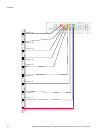
2 Slide the chassis assembly onto the rack rails until the front flanges engage on the rack.
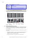
3 Ensure the chassis is centrally located. If in doubt about correct orientation, the drive bays (at
front) should have their black drive connectors toward the bottom of each bay.
4 Screw the 4 front rack mount screws through the flanges and tighten.
5 Fit and tighten the rear hold down screws ensuring the enclosure is in tight contact to both the
side and top of the chassis to avoid any movement of the chassis in the rack.
2.3 Power Supply/Cooling Module Installation
• Two power supply/cooling modules to be installed in the rear of the enclosure in positions
1 and 5.
2.3.1 Parts Check List
• 2 x AC, 450W Power Supply/Cooling Modules
2.3.2 Power Supply/Cooling Module Procedure
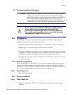
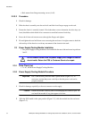
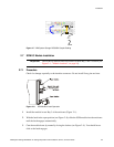
Important PSU1 (RH rear bay) must be fitted “upside-down”(Figure 2–1). If
necessary, reorient the power cord clip so that the power cord can be
properly retained.
1 Check for damage, especially to the rear connector on the supply.
Caution Handle the module carefully and avoid damaging the connector pins. Do
not install the module if any pins appear to be bent.
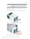
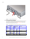
2 With the PSU handle in the open position (Figure 2–2), slide the module into the enclosure
(Figure 2–3).
Do not remove covers from the power supply unit. Danger of electric
shock inside. Return the PSU to Customer Service for repair.
!
Warning